


Rev. A.3, 5/00 Page- 1
SECURITRON 32, 34, 62 AND 82 SERIES MAGNALOCK
INSTALLATION INSTRUCTIONS
1. DESCRIPTION
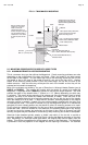
Securitron’s Magnalock family represents the state of the art in electric locking. Three different
size models are available: The Model 32 and Model 34 series with a holding force of 600 lbs.
(275 Kg.); The Model 62 series with a holding force of 1,200 lbs. (550 Kg.) and the model 82
series with a holding force of 1,800 lbs. (820 Kg.). Several mounting and electronic options
are available which are described in this manual. Note that most points in this manual apply to
the entire Magnalock series. When a point applies to a particular Magnalock version, this will
be specifically noted.
2. PHYSICAL INSTALLATION
2.1 SURVEY
Because of the wide variety of situations in which the Magnalock may be utilized, first survey
the physical area in which it is to be installed and determine the best method of mounting it. In
this initial planning two considerations come into play: the mounting method must be strong
enough so that the full holding power of the Magnalock can be effective, and the Magnalock
and wiring must be protected to a reasonable degree from damage by intruders or vandals.
Often an accessory bracket is necessary, either furnished by Securitron or made up by the
installer. The brackets that can be used are covered later. Note that Magnalocks are supplied
with a complete set of fasteners. When shipped outside of North America, metric fasteners are
supplied and therefore the drawings in this manual show both US and metric fasteners.
2.2 INSTALLATION TOOL KIT
Securitron offers an installation tool kit (part # IK or IKM, for metric use) which includes special
drills, a drilling template, a blind nut collapsing tool and extra fasteners and hardware. If the
installation is for a large number of locks or if the installer expects to perform other installations,
we recommend the purchase of this kit as it reduces installation labor and improves job quality.
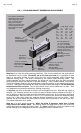
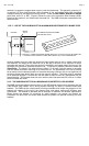
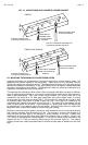
2.3 GENERAL INSTALLATION ON OUTSWINGING DOOR
The Magnalock should be mounted under the door frame header in the corner farthest from the
hinges (see Figure 4). Most commonly, it is positioned horizontally but vertical positioning
should also be considered. In some cases for example, the horizontal header on an aluminum
frame glass door is not as strong as the vertical extrusion, so vertical mounting would be
preferred. This type of installation places the Magnalock such that the door swings away from
it. This configuration is necessary for all facility exit doors (otherwise, the Magnalock would be
on the outside of the building). For interior doors, the Magnalock should still be mounted in
this manner unless security planning anticipates a physical assault on the Magnalock from that
side of the door in which case see section 2.4 on inswinging door installation.
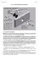
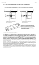
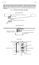
2.3.1 STRIKE PLATE MOUNTING
The strike should be mounted before the magnet on the upper corner of the door. The first
step is to locate the precise place you intend to mount the strike including deciding whether
you want to mount the Magnalock horizontally or vertically (see Section 2.3.2). The top of the
strike should be positioned about 1/10" (2.5mm) below the line where the door meets the
door stop, or below the header if there is no door stop to permit free closing. If the strike is
mounted vertically instead of horizontally, increase this stand-off distance to 2/10" (5mm).
More clearance is needed on a vertical mount because the strike projects out from the door and
can scrape the side frame as the door swings closed on its arc. Final positioning of the strike is
dictated by the desired position of the magnet. The strike must be centered on the magnetic
poles (3 bars) and the magnet is normally moved an inch or so in (or down) from the frame
corner so that the magnet mounting holes will not have to be drilled awkwardly in the corner.
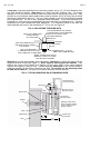
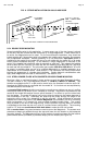
When the strike position has been chosen, step two is to drill three holes in the door following
the template. Step three is mounting the white plastic bushings which surround and insulate
the roll pins into the 1/2" (12.7mm) holes. The bushings are employed to insulate the strike
electrically from a metal door and also help prevent the roll pins from wearing the door.