


Rev. A.3, 5/00 Page- 3
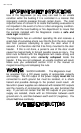
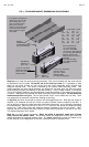
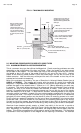
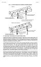
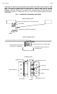
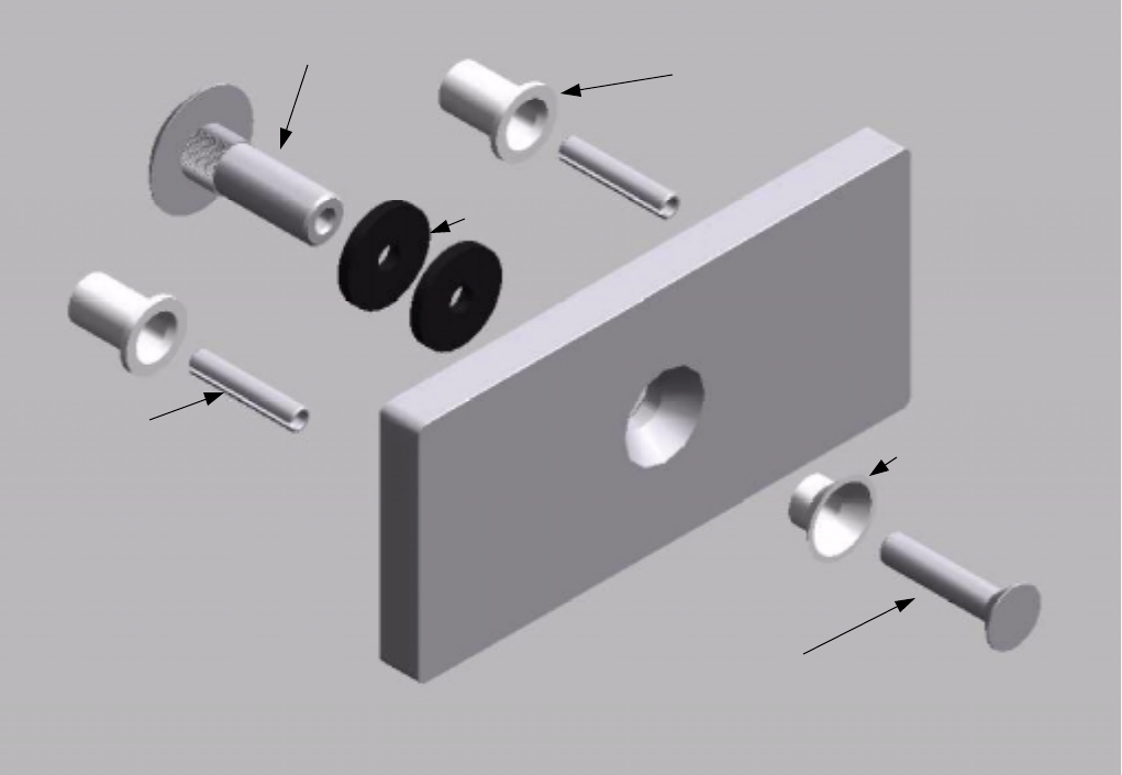
FIG. 2: STRIKE DIMENSIONS AND ASSEMBLY
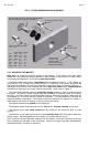
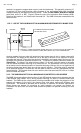
2.3.2 MOUNTING THE MAGNET
Step one is to locate the mounting position of the magnet. It will mount in the door frame
header with four socket cap machine screws for metal frames or wood screws for wood frames.
In mounting the Magnalock, six conditions must be followed:
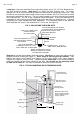
-- The frame header must present a flat surface for the magnet to mount to. 1 7/8” (48mm) for
the model 34, 2 1/4” (57mm) for the model 32 and 2 1/2" (63.5mm) for the model 62 and 82 are
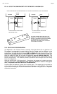
required from the door to the rear of the magnet for proper mounting (as shown in Figure 4). If
this length of flat surface is not available, the use of stop filler plates and/or header brackets
available from Securitron can usually resolve the problem. Again, refer to Figure 4.
-- The frame area selected must be structurally strong enough to yield a properly secure
installation. The issue of frame strength must be considered in selecting vertical or horizontal
mounting. One often finds on aluminum headers that the horizontal extrusion is weak and can
be snapped off, so vertical mounting would be preferred. It is also possible to reinforce the
header by adding a steel plate. The installer must avoid mounting the magnet to a wobbly or
weak support or the intrinsic security of the lock will be diminished.
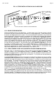
-- The magnet face must be parallel to the strike plate.
-- The magnetic poles (three metal bars on the Magnalock), must be centered on the strike.
-- The magnet must make solid contact with the strike but still allow the door to close
properly.
-- The direction of door opening must pull the strike directly away from the magnet rather than
sliding it away. Electromagnets hold only weakly in the shear direction of pull.
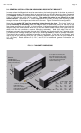
Once a solid flat surface has been prepared for the magnet, it must be positioned so that its
face is parallel and centered to the strike plate. When the magnet has been experimentally
positioned this way, it's ready for mounting.
Sex Bolt, Models 32, 62, 82, PN# SB-1, SB-1M (Metric)
Model 34, PN# 330-12100, 330-12150 (Metric)
Bushing (2), PN# 560-12050
Roll Pin (2), PN# 330-10800
1/4" x 1 1/4"
R
u
b
b
e
r
W
a
s
h
e
r
(
2
)
P
N
#
R
W
-
1
(
P
a
c
k
o
f
2
4
)
Bushing,
PN# 330-12000
Flathead Screw
5/16-18 x 1 3/4"
PN# 300-13600 or
8mm-1.25mm x 40mm
PN# 300-13750 (Metric)
Length Width Depth
32 6.25" 1.63 .5
(mm) 158.8 41.4 12.7
34 6.4" 1.44 .44
(mm) 164.5 37 11.3
62 6" 2.75 .5
(mm) 152.4 70 12.7
82 9.5" 2.75 .5
(mm) 240 70 12.7