


Rev. A.3, 5/00 Page- 13
3. ELECTRICAL INSTALLATION
3.1 GENERAL ELECTRICAL CHARACTERISTICS
The Magnalock constitutes a low current electric load. Owing to internal circuitry, the
Magnalock does not show the normal characteristics of an electromagnetic or other inductive
load. Inductive kickback is suppressed, so arcing across switch contacts need not be a
concern. This suppression also protects nearby access control or computer equipment from
possible interference. The circuitry performs the additional functions of canceling residual
magnetism ("stickiness" on release) and accelerating field collapse so that the Magnalock
releases nearly instantly when power is removed. Electrically speaking, the load is nearly pure
resistive in nature although there is a modest capacitive component which depends on the
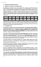
series. The following chart shows the current draw for each version and the degree of internal
capacitance.
32 @ 12V 32 @ 24V 34 @ 12V 34 @ 24V 62 @ 12V 62 @ 24V 82 @ 12V 82 @ 24V
CURRENT 300 mA 150 mA 350 mA 175 mA 250 mA 125 mA 350 mA 175 mA
CAPACITANCE 0 0 0 0 30 Mfd 15 Mfd 30 Mfd 15 Mfd
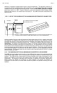
Capacitance can be an issue if very sensitive switch contacts are used to control the Magnalock
(such as a low current reed switch). A capacitive load includes some inrush current which can
stress these contacts. Note however that the problem is diminished when the Magnalock is
mounted some distance from the control switch as the interconnecting wiring adds a series
resistance to the circuit which sharply limits the inrush.
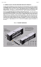
3.2 STANDARD LOCK
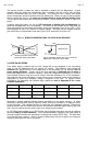
For operation, DC voltage must be provided to the lock. The red wire receives +12VDC or
+24VDC, and the black wire, 0V (negative). If the lock is connected with reverse polarity, it
will not function at all. The voltage source may be regulated, filtered or pulsating DC
(transformer + bridge rectifier). Half wave pulsating DC generated by a transformer and
single diode will not properly operate the Magnalock. An exact voltage level is not
necessary. Less than standard voltage will proportionately reduce holding force but will cause
no harm. Overvoltage up to 30% is acceptable.
The model 34, 62 and 82 series Magnalocks are
dual voltage units. This means that you can
apply either 12 or 24 volts to the same unit and it will operate equally well. Dual voltage
Magnalocks are auto-switching which means that you still apply power to the red and black
wires, while observing correct polarity. The lock, however, automatically detects whether it is
receiving 12 or 24 volts and draws the correct amount of current for that voltage (the current is
twice as high when the lock is receiving 12 volts than when it is receiving 24 volts). The model
32 series has separate models for 12 and 24 volt operation.
It is good practice to use power supplies with 1/3 extra capacity beyond the current
requirements of the load. This greatly reduces the possibility of heat induced power supply
failure and also allows for future expansion. Power supply cost is a small fraction of the job
cost and should not be skimped on.
Switches may be wired as necessary between the Magnalock and power source. Internal
circuitry eliminates inductive kickback, so neither electromechanical switches nor solid state
devices will be damaged by arcing when the Magnalock is shut off.
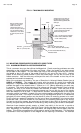
3.3 AVOIDING POOR RELEASE CHARACTERISTICS
One of the exceptional features of Magnalocks is near instantaneous release. This is
particularly valuable when the lock is being switched off and the door is being opened at the
same time as occurs when a switched exit device like Securitron’s Touch Sense Bar is being
used. Two separate wiring errors can however cause Magnalocks to release slowly (in one or
two seconds) and this is annoying.
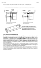
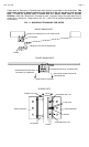
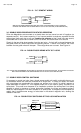
The first problem is
connection of a reverse diode in parallel with the lock's power input.
This is often done to suppress inductive kickback from a coil such as a relay coil or solenoid.
Magnalocks already have internal inductive kickback protection, so addition of a reverse diode
is pointless. The diode does act to "recirculate" current flow through the magnet coil and
thereby considerably slows release. A diode should never be connected as shown in Figure
12.