


Ensure that the inverter’s power switch is in the “OFF” position. LEAVE the power switch in the
“OFF” position at all times. The interface board will activate the inverter when necessary. If the
inverter power switch is placed in the “ON” position, it will cause a continuous drain on the
external 12-volt power system.
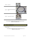
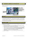
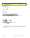
• Remove the screws from the rear cover of the inverter and remove the cover.
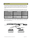
• Place the wires from the external DC source (battery) and the wires from the DC power
cable through the holes in the end plate.
• Connect cables from the external 12-volt power source and the DC power cable assembly to
the appropriate positive (+) and negative (-) terminals on the back of the inverter and tighten
the hold down screws.
• Connect the yellow wire from the DC power cable to the “REMOTE” terminal on the
power inverter and tighten the hold down screw.
• Reinstall the cover.
• If the external 12volt lines are not powered, power them now. (Connect them to the battery)
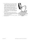
• Connect the instrument’s AC power cord between the instrument and
the front of the power inverter.
• Turn the instrument “ON.”
• Press the “REGEN” switch on the instrument. Inverter operation can
be verified in either of two ways:
Immediately after pressing “REGEN” the inverter will intermittently
“sing.” This tone slowly becomes nearly continuous and then ends
after 64 seconds.
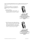
If the area is noisy, use a voltmeter or test lamp to verify that
approximately 115 volts is present for about 64 seconds, starting
when the “REGEN” switch is pressed.
• Allow the instrument to complete its regeneration before turning it off.
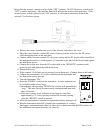
• With the instrument turned off, complete the installation (i.e. connect
data logger, communications cables, or other devices and ensure that the DIP switches for
the instrument and option board are set correctly.
AZI Customer Service 800-528-7411 or 602-470-1414 Page 47 of 50