


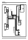
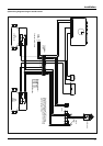

38
boiler protection devices
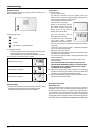
Boiler protection devices
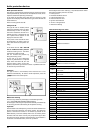
The boiler is protected from malfunctioning by means of internal
checks performed by the electronic microprocessor P.C.B., which
stops the boiler from operating if necessary.
In the event of the boiler being shut o in this manner, a code
appears on the display which refers to the type of shut-o and the
reason behind it.
There are two types of shut-o :
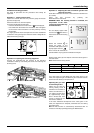
Safety shut-o
This type of error is “volatile”, which
means that the boiler starts up again
automatically as soon as the prob-
lem which caused the shut-o is re-
moved; the error is indicated by the
«Err» symbol which appears on the
display and the error code.
In fact, soon as the cause of the shut-
o disappears, the boiler starts up
again and continues to operate nor-
mally.
In the event of error 1 08 - Shut-o
due to insu cient water pressure
inside the heating circuit - the boiler
will perform a safety shut-o .
You can increase the pressure by
lling the heating circuit.
In this case or if the re-balancing
request is performed on a frequent
basis, switch the boiler o , turn the
external electric switch to the OFF
position, shut o the gas cock and contact a quali ed technician
to check for any leaks of water.
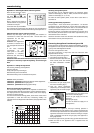
Shutdown
This type of error is “non-volatile”, which means that it is not
removed automatically. To restore normal operation press the
button on the control panel.
Malfunction warning
This warning is shown by the display in the following format:
5 P1 = FIRST IGNITION ATTEMPT UNSUCCESSFUL
the rst gure indicating the operational assembly is followed by
a P (warning) and the code relating to the speci c warning.
Important
If this shutdown occurs frequently, contact an authorised Technical
Service Centre for assistance. For safety reasons, the boiler will
permit a maximum of 5 resets in 15 minutes (5 presses of the
RESET button); at the 6th attempt within this 15-minute period
the boiler will shut down and may only be operated again after
the electricity supply has been disconnected. If the shutdown is
occasional or an isolated event, this is not a problem.
The rst gure of the error code (e.g. 1 01) indicates within which
operational assembly the error occurred.
1 - Primary Circuit
2 - Domestic Hot Water Circuit
3 - Internal Electronic Part
4 - External Electronic Part
5 - Ignition and Detection
6 - Air inlet - ue gas outlet
7 - Multi-zone Heating
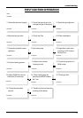
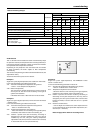
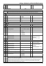
Table summarising error codes
Central Heating circuit
Display Description
1 01
Overheat
1 02
Pressure Sens Error
1 03
Insu cient circulation
1 04
1 05
1 06
1 07
1 08
Insu cient water (request lling)
1 10
C.H. Flow temp. probe circuit open / short circuit
1 12
C.H. Return temp. probe circuit open / short circuit
1 14
External sensor circuit open / short circuit
1 16
Floor Thermostat contact open
1 18
Heating delevery probe problem
1 P1
Insu cient circulation indication
1 P2
1 P3
D.H.W. circuit
2 02
Bottom storage temperature probe open /
short circuit
Solar kit
(optional)
2 04
Solar collector temperature probe open /
short circuit
2 07
Solar collector overheating
2 08
Collector frost protection temperature
Internal P.C.B.’s
3 01
EEPROM error
3 02
Comunication error
3 03
Main P.C.B. error
3 04
Too many (> 5) resets in 15 minutes
3 05
Main P.C.B. error
3 06
Main P.C.B. error
3 07
Main P.C.B. error
External P.C.B.’s
4 07
Room sensor circuit open/short circuit
Ignition and Detecion
5 01
No ame detected
5 02
Flame detected with gas valve closed
5 04
Flame lift
5 P1
1st Ignition Failed
5 P2
2nd Ignition Failed
5 P3
Flame cut-o
Air Inlet / Flue gas outlet
6 04
Insu cient fan speed
6 10
Thermofuse open