


20
installation
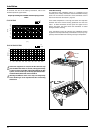
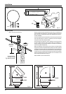
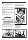
Fitting the 5” Flue
(Ø 80 / 125 Horizontal/vertical)
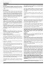
Once the boiler has been positioned on the wall, it is necessary to
insert the Ø80/125 adaptor (Fig. 5) for both horizontal and vertical
ue runs into the boiler ue socket (not supplied with ue kit -
Part No 3318095).
Push the adaptor onto the boilers ue connection, grease the seals
then add extensions or elbows as required, secure the adaptor,
using the clamp and screws provided.
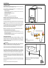
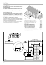
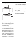
To t extensions or elbows it is rst necessary to ensure that the
lip seal is tted correctly into the inner ue, once veri ed, it is
simply necessary to push them together, no clamps are necessary
to secure the ue components.
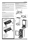
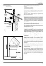
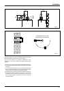
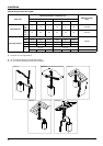
Before proceeding to t the ue, ensure that the maximum ue
length has not been exceeded (See the tables) and that all elbows
and bends have been taken into consideration, for each additional
90° elbow 1 metre must be subtracted from the total ue length,
and for each 45° 0.5 metres must be subtracted from the total ue
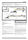
length (the height of the vertical adaptor and a 45° bend can be
seen in Fig.6 and a 90° bend in Fig. 7).
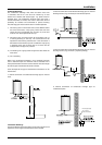
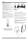
Note: DO NOT cut the vertical ue kit.
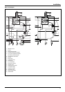
180 mm
Total length
of Vertical Kit
1240 mm
5" Adaptor
Part no: 3318095
* This length will vary
according to the type
of ashing installed
Useable length
of Vertical ue
575 mm*
Fig. 5
Clamp
Seal
Screws
Fig. 4
Fig. 6
Fig. 7