


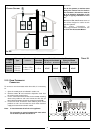
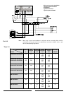
Exhaust
Type
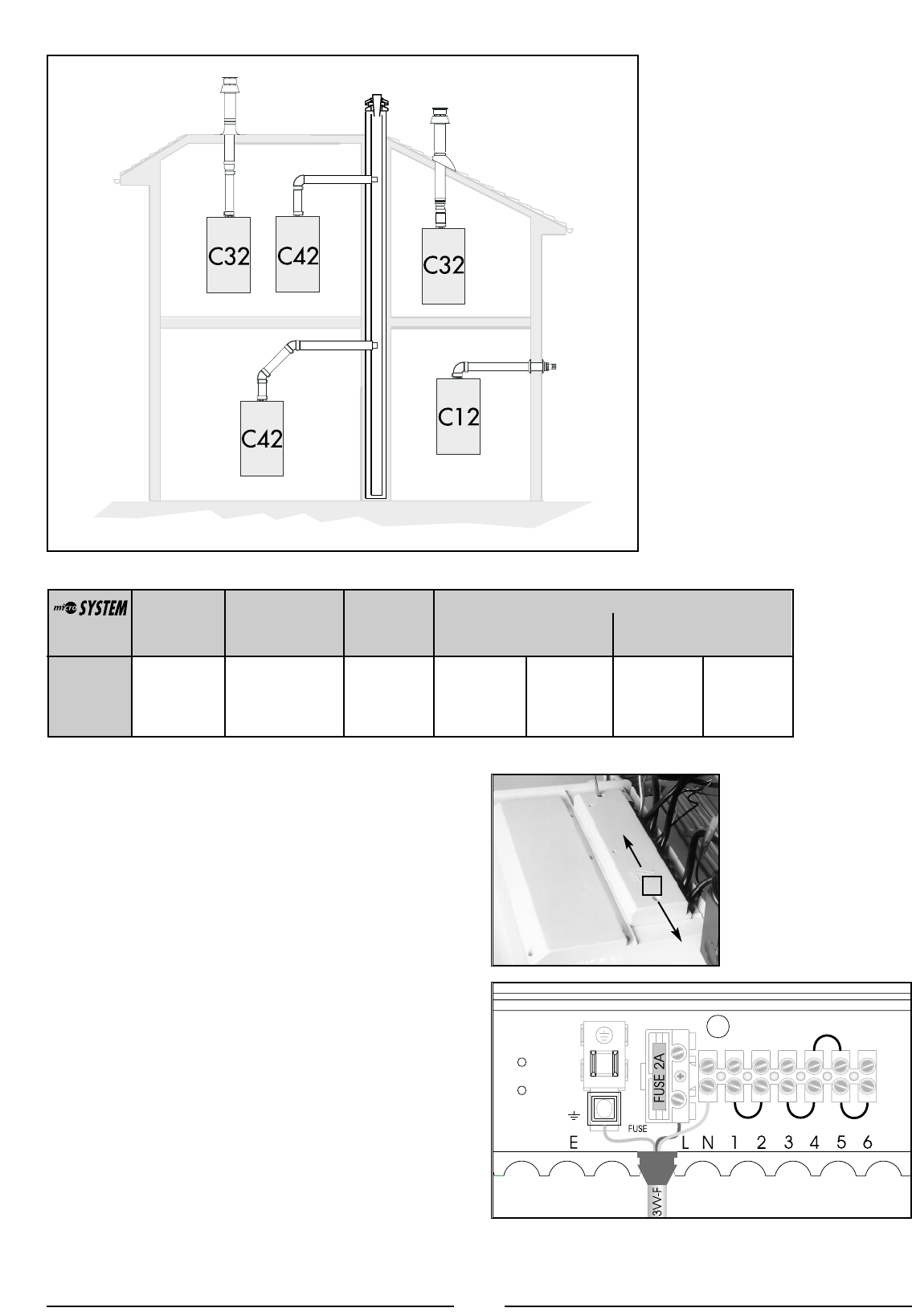
C12 (xx)
C32 (xx)
C42 (xx)
Restrictor
ø 44 mm
L min = 0.5 m
L max = 1 m
Maximum
Extension
Exhaust/Air
L = 5 m
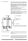
Risk of Condensation Forming
Coaxial
Systems
ø 60/100
Piping not insulated
ø 44
restrictor NO restrictor
NONE NONE
Piping insulated
ø 44 restrictor NO restrictor
NONE NONE
T
ABLE 2.1
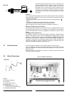
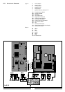
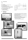
10 RFFI
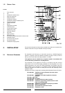
To connect a room thermostat and/or time clock, it is necessary
to:
1. - Open the control panel as indicated in section 4.3;
2.- Remove screws “A” and remove the inspection cover from
the reverse of the control panel;
3. - For the room-thermostat connect the thermostat switching
wires to the position 5 and 6 and remove the wire link (for
three-wire thermostats connect the neutral to terminal N);
4. - For the time clock connect the clock switching wires to the
positions 3 and 4 and connect the clock motor electrical
supply to the terminals marked L and N.
Note: A frost thermostat is built-in to the appliance.
For connection to control systems with zone valves
for hot water cylinders see section 3.
2.10 R
OOM THERMOSTAT
CONNECTION
A
9
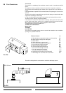
IMPORTANT!
For all flue systems, a restrictor must
always be inserted into the boiler’s
flue connector; the restrictor must be
Ø 44 in diameter depending on the
length of piping indicated in T
ABLE
2.1.
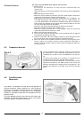
FIG 2.9 and FIG 2.10 illustrate some of
the various designs for coaxial or twin
pipe flue systems.
For further information on
discharge/ventilation accessories, see
the F
LUE
PIPE ACCESSORIES MANUAL
.
COAXIAL SYSTEMS
FIG. 2.9