


16
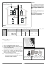
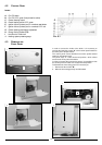
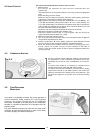
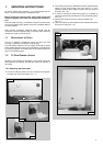
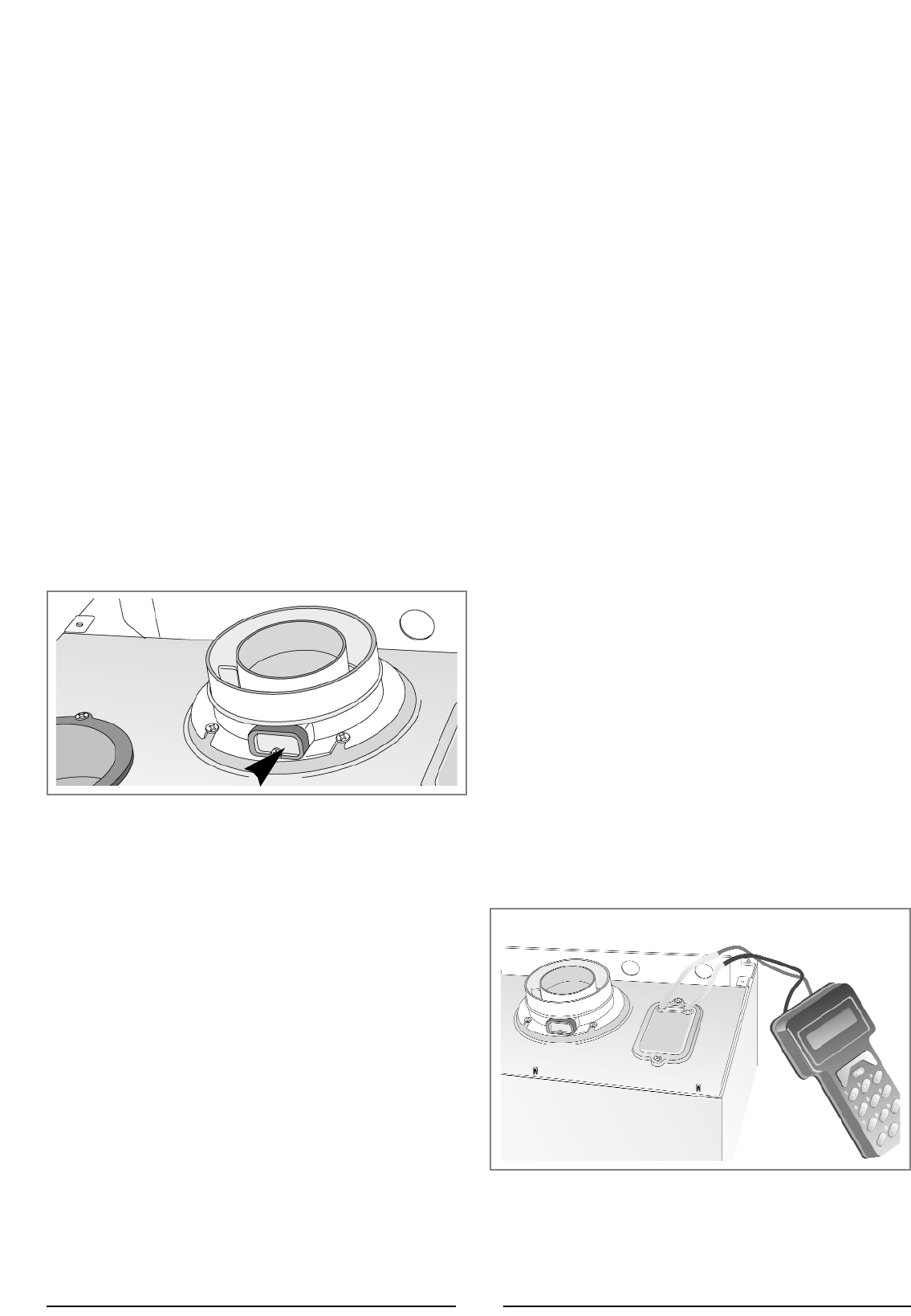
The flue connector has two apertures, readings can be taken for
the temperature of the combustion by-products and of the
combustion air, as well as of the concentrations of O
2
and CO
2
,
etc. .
To access these intakes it is necessary to unscrew the front
screw and remove the metal plate with sealing gasket.
To achieve the best test conditions, turn the central heating
adjustment knob “G” to the “max” position and remove the
electrical connection to the heating sensor (see section 6.). This
will allow the appliance to operate at the maximum heating
power.
4.5 C
OMBUSTION
ANALYSIS
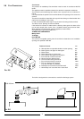
4.4 INITIAL START-UP
T
HE CHECKSTO BE RUN BEFORE INITIAL START-UP ARE AS FOLLOWS:
1. Make sure that:
-the screw on the automatic air valve has been loosened when the
system is full;
- If the water pressure in the system is below 1.5 bar, bring it up to the appropriate
level;
- Ensure that the gas cock is closed;
- Make sure that the electrical connection has been made properly and that the
earth wire is connected to an efficient earthing system;
- Supply power to the boiler by pushing the On/Off button “A” (see F
IG.4.1) - the
L.E.D. “B” will illuminate. Then push the button “C” in for central heating - the
L.E.D. “D” will illuminate.This will start the circulation pump. After 7 seconds, the
boiler will signal a shutdown due to ignition failure. Leave the boiler as it is until
all of the air has been bled from the system.
- Loosen the cap on the head of the pump to eliminate any air pockets;
- Repeat the procedure for bleeding the radiators of air;
-Check the system pressure and, if it has dropped, open the filling loop
again to bring the pressure back up to 1.5 bar.
2. Make sure that all gate valves are open;
3. Turn on the gas cock and check the seals on the connections with an approved
soap solution and eliminate any leaks.
4. Press the reset button “E” for the lighting system; the spark will light the main
burner. If the burner does not light the first time, repeat the procedure.
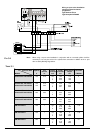
5. Check the minimum and maximum pressure values for the gas going to the
burner; adjust it if needed using the values indicated in the table in
section 5 (See the relative section for burner pressure adjustment within the
servicing manual).
FIG. 4.2
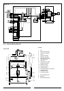
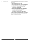
In the boiler, it is possible to monitor the correct operation of
the flue exhaust/air intake, checking for a loss of general
pressure in the system. Through the use of a differential
manometer connected to the test points of the combustion
chamber, it is possible to detect the ∆P of operation of the air
pressure switch.
The value detected should not be less than 0.5 mbar under
conditions of maximum thermal power in order for the boiler
to function properly and without interruption.
4.6 FUME DISCHARGE
MONITORING
FIG. 4.3