


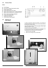
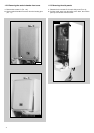
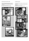
2. The control panel moves downward and when pulled forward,
rotates on two lateral hinges; the panel stays in a semi-
horizontal position, which allows access to the inner parts of
the boiler (F
IG. 1.2);
3. In order to increase the manouvering space, it is possible to
raise the control panel and rotate it to a fully horizontal position
(F
IG. 1.3);
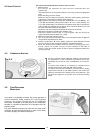
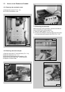
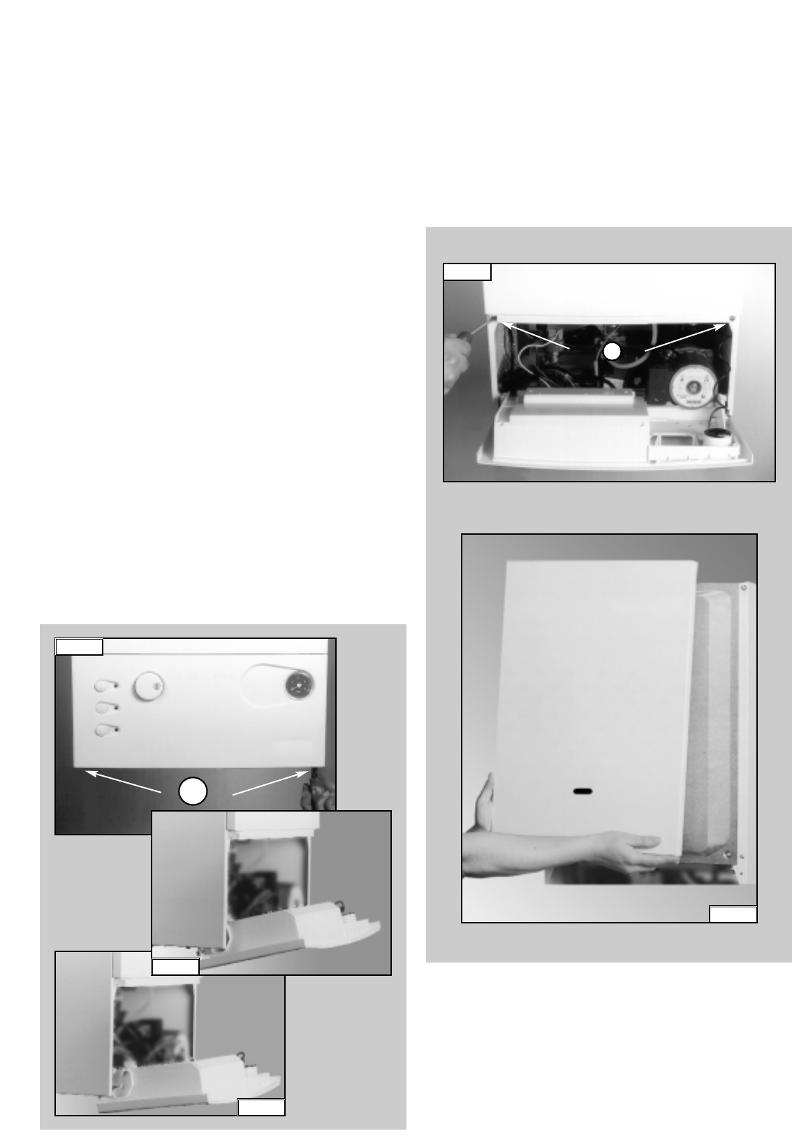
4. Remove the screws “B” from the front panel bottom lip
(F
IG. 1.4);
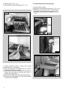
5. Lift the front panel up and forward from the raised screws at the
the top of the casing (F
IG. 1.5).
FIG. 1.4
B
FIG. 1.5
3
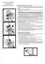
1. SERVICING INSTRUCTIONS
The life of individual components varies and they will need
servicing or replacing as and when faults develop.
The fault finding sequence chart in chapter 2 will help to locate
which component is the cause of any malfunction, and instructions
for removal, inspection and replacement of the individual parts are
given in the following pages.
1.1 R
EPLACEMENT OF PARTS
1.2 TO GAIN GENERAL ACCESS
All testing and maintenance operations on the boiler require the
control panel to be lowered. This will also require the removal of
the casing.
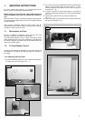
1.2.1 Removing the front panel
1. Loosen the fastening screws “A” of the control panel located on
the lower part of the panel itself. (F
IG. 1.1);
A
FIG. 1.3
F
IG. 1.1
FIG. 1.2
To ensure efficient safe operation, it is recommended that the
boiler is serviced annually by a competent person.
Before starting any servicing work, ensure both the gas and
electrical supplies to the boiler are isolated and the boiler is
cool.
Before and after servicing, a combustion analysis should be made
via the flue sampling point (please refer to the Installation Manual
for further details).
After servicing, preliminary electrical system checks must be
carried out to ensure electrical safety (i.e.polarity, earth continuity,
resistance to earth and short circuit).