


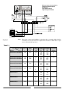

6
The boiler operates with alternating current, as indicated in the
technical information table in section 7, where the maximum
absorbed power is also indicated. Make sure that the
connections for the neutral and live wires correspond to the
indications in the diagram.The appliance electrical connections
are situated on the reverse of the control panel under the
inspection cover (see the servicing manual for further
information)
I
MPORTANT!
In the event that the power supply cord must be changed, replace it with one with the
same specifications. Make the connections to the terminal board located within the
control panel, as follows:
- The yellow-green wire should be connected to the terminal marked with the “”
symbol;
- The blue wire should be connected to the terminal marked “N”;
- The brown wire should be connected to the terminal marked “L”.
Note: The diagrams for the electrical system are indicated in section 2.12.
Warning, this appliance must be earthed.
External wiring to the appliance must be carried out by a competent person and be
in accordance with the current I.E.E. Regulations and applicable local regulations.
The microSYSTEM range of boilers are supplied for connection to a 230 V
~
50 Hz
supply.
The supply must be fused at 3 A.
The method of connection to the electricity supply must facilitate complete electrical
isolation of the appliance, by the use of a fused double pole isolator having a contact
separation of at least 3 mm in all poles or alternatively, by means of a 3 A fused
three pin plug and unswitched shuttered socket outlet both complying with BS 1363.
The point of connection to the Electricity supply must be readily accessible and
adjacent to the appliance unless the appliance is installed in a bathroom when this
must be sited outside the bathroom (see section 2.2).
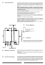
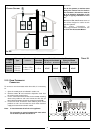
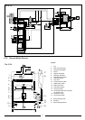
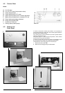
E
L
N
F
IG. 2.2
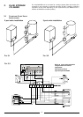
2.8 WATER CONNECTIONS
2.7 GAS CONNECTION
The local gas region contractor connects the gas meter to the service pipe.
If the gas supply for the boiler serves other appliances ensure that an adequate
supply is available both to the boiler and the other appliances when they are in use
at the same time.
Pipe work must be of an adequate size. Pipes of a smaller size than the boiler inlet
connection should not be used.
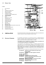
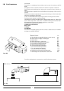
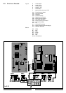
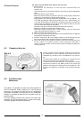
FIG. 2.4
VIEW OFTHE BOILER CONNECTIONS
FIG. 2.3
A
D
LEGEND:
A = Central Heating Flow
C = Gas Inlet
E = Central Heating Return
F = Safety Valve
G = Pump transportation screw
(remove before igniting the boiler)
H = Automatic By-pass pipe
F
B
C
E
SC004A