


8
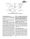
heater. Use the adhesive tape which is included
in the package to stick the pattern to the wall.
Keep in mind that the heater needs to have cer-
tain minimum clearances (See paragraph 7 on
this page), and that the heater must be level. Drill
four holes into the wall at the studs (16 inches on
center) as indicated on the template. Use a 1/8
inch drill if screws are to go directly into wood or
1/4 inch if plastic anchors are to be used.
WARNING: Be sure to remove the paper
template before hanging the heater on the
wall.
After the paper template is removed, insert the
mounting screws into the two upper holes. Leave
1/2 inch between the wall and the screw head, in
order to have enough space for your unit to slip
over. The bottom screws will secure the Water
and Gas Connecting Strip Assembly to the wall.
Next remove the front panel. To do this, remove
the temperature selector knob (H) and the pilot
starting button by pulling them out. Unscrew the
screws under each front corner. Lift the panel up
and pull out. At this point, you can either screw
the two large screws to fasten the Water and Gas
Connecting Strip Assembly to the wall using the
pre-drilled holes and connect your pipes directly
to the water heater, or you can remove the heater
from the Water and Gas Connecting Strip Assem-
bly in order to connect the piping, and then re-
connect the heater later. If you decide to connect
the pipes directly, skip the next section and go to
#3, "Connecting the Gas Line."
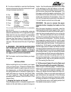
2. To Disconnect Heater From the Water and
Gas Connecting Strip Assembly (Optional)
Refer to figure 3 (following page). Unscrew each
brass union nut at the three points marked in fig-
ure 3. Be careful not to lose the washers. Re-
move your heater from the Water and Gas Con-
necting Strip. Now you can make your water and
gas connections as explained in the following
sections. When all connections have been made,
re-hang the heater on the upper screws and re-
connect the brass union nuts making certain that
the washers are properly in place.
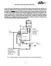
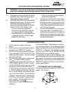
8. For alcove installation, maintain the following
minimum clearances from all construction for ser-
vicing and proper operations:
Alcove Closet
A. Top 6 inches 12 inches
B. Front OPEN 6 inches
C. Back 0 inches 0 inches
D. Sides 1 inch 1 inch
(Left side 6" for service)
E. Floor 6 inches* 12 inches*
F. Flue 6 inches 6 inches
(single wall only)
*Do not install over floor covering which is combustible,
such as carpet.
Minimum clearance to combustible materials
should not be less than 6" for single wall flue pipe.
Note that this can be reduced if combustible
materials are protected as per table VI of the
National Fuel Gas Code or if Type B gas vent is
used. (Follow the minimum clearances for the
vent type. We recommend the use of Type B gas
vent.
9. WARNING: THIS WATER HEATER DOES
NOT STORE ANY HOT WATER. DO NOT IN-
STALL IN AN AREA WHERE IT COULD
FREEZE. This heater is neither designed for
nor approved for outside installation.
10. The heater must be level before you begin
the piping.
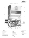
INSTALLATION
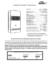
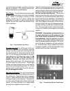
Before installing the unit, be certain your heater
is for your type of gas - Propane or Natural Gas.
Identification labels for type of gas are found on
the shipping box, on the right side panel and on
the rating plate which is located in upper part of
draft hood seen by removing front panel (See
"X" Fig. 2, page 6). Also, each gas orifice is
stamped with a number (75 for LPG and 115 for
Natural Gas).
1. Hanging the heater on the wall
Place the paper pattern or template (supplied with
heater) on the wall where you plan to hang your