


10
Sweat your cold water pipe to the AquaStar inlet
elbow fitting. NOTE: The inlet filter screen and
water flow restrictor can be damaged by heat
if the cold water inlet elbow is attached to
the AquaStar when it is sweated to the cold
water inlet pipe. The inlet and outlet elbow fit-
tings seal by means of a union connection with a
washer type gasket at the joint. Although these
fittings have 1/2" threads, NPT fittings should not
be substituted for these elbows and no pipe dope
or thread tape is to be used at the joints. Be cer-
tain there are no loose particles or dirt in the pip-
ing. Blow out or flush out the lines before con-
necting to the AquaStar.
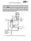
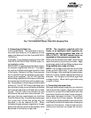
5. Connecting the pressure relief valve
A temperature and pressure relief valve must be
installed on the hot water line, close to the heater.
No valve is to be placed between the relief valve
and the heater. Installation shall be made in such
a manner that the discharge from the tempera-
ture and pressure relief valve will be conducted
to a suitable place for disposal when relief oc-
curs. No reducing coupling or other restriction
may be installed in the discharge line. The dis-
charge line must be installed such that it allows
complete drainage of both the valve and the line.
The location of the relief valve must be readily
accessible for servicing or replacement. To ac-
commodate the pressure relief valve, a suitable
fitting connected to an extension of a "T" fitting
can be sweated to the line. Make the T-fitting
extension long enough to ensure that the tempera-
ture probe does not interfere with the water flow.
The relief pressure of the valve must not exceed
150 psig. The relief temperature of the valve must
not exceed 210ºF and the discharge capacity
must be at least 125,000 Btu per hour.
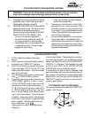
6. Vent pipe connection. WARNING: Do not
reduce the vent pipe size.
This appliance must be vented to the outside fol-
lowing all local ordinances and specifications for
installing a gas appliance vent or chimney. The
gasses to the outdoors under all operating con-
venting system must be constructed so as to
develop a positive flow adequate to remove flue
ditions.
The appliance must be located as close as prac-
ticable to a chimney or vent. The vent pipe sec-
tions must be fastened with sheet metal screws.
Keep in mind the minimum clearance from the
top of your heater. Remember also that single
wall vent pipe connectors require a 6 inch clear-
ance from combustibles. National Fuel Gas Code
specifies double wall - Type "B" - vent pipe be
used in cold climates and for gas vents running
through attics. We consider double wall vent pipe
preferable in all circumstances. The vent con-
nector should have as much vertical rise as pos-
sible (minimum 12") before any horizontal run.
Any vent section greater than 45 degrees from
vertical is considered horizontal. Horizontal sec-
tions of vent connectors must slope upwards at
least 1/4 inch for every foot of its horizontal length.
Keep the horizontal section short and avoid too
many elbows.
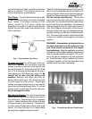
Note: Although the AquaStar has the same vent-
ing requirements as other Category I gas appli-
ances, certain features and specific use charac-
teristics make it more important to have a vent-
ing system which exceeds minimum standards.
AquaStar thermostats modulate burner output.
Therefore, when operating at less than full out-
put, the heater does not have its full heating ca-
pacity to warm the flue pipes to create a natural
draft. Most gas appliances have longer duty
cycles than are typical of instantaneous heaters.
For these it is considered sufficient if the appli-
ance can overcome a downdraft within the first
five minutes of operation. An instantaneous "on
demand" heater like the AquaStar may have
frequent operating cycles of less than a minute.
If venting and air supply are inadequate to pro-
vide a positive draft as soon as the heater turns
on, the heater may not remain on long enough to
establish a positive draft. See venting guide on
page 27.