6
WARNING
Note: The burners of an instantaneous “on demand” water
heater such as the AquaStar are only on at the time that
hot water is actually being used, the venting stack is
therefore cold except for the short durations when hot water
is being used, it is therefore very important that the venting
and air supply be adequate to provide a good positive
draft as soon as the burners turn on.
The AquaStar 38B instantaneous water heaters have built-
in draft diverters and are designed for indoor installation
only. The draft diverter outlet must be connected to a clear,
unobstructed vent of the same size, or larger.
In Canada, CAN/CGA-B149 Installation Code for
detailed requirements
In U.S.A., ANSI Z223.1 - NFPA 54, national Fuel Gas
Code for detailed requirements.
GAS CONNECTIONS and Gas Regulator
Before connecting the gas supply, check the rating plate
on the right side of the front cover to be sure that the heater
is rated for the same gas to which it will be connected.
In the United States: The installation must conform with
local codes or, in the absence of local codes, the National
Fuel Gas Code ANSI Z223.1/NFPA 54.
In Canada: The Installation should conform with CGA B149
INSTALLATION CODES and /or local installation codes.
NOTE: The Aquastar 38 B is supplied with a gas
pressure regulator that must be installed on the heater
before attaching the gas supply line. See figure 2.
Place the gas regulator between the gas supply
connection (wich comes with a manual shutoff valve)
and the gas fitting wich is connected to the heater’s
gas inlet. There is a pressure test nipple on this gas
fitting. The regulator supplied with the heater is preset
for the gas shown on the rating plate to the correct
pressure. It is an appliance level regulator designed
for (low inlet) pressure (less than 1/2 Psig or 15” W.C.)
DO NOT connect to an unregulated or high pressure
propane line or to a high pressure commercial natural
gas line.
National Fuel Gas Code requires that a sediment trap (drip
leg) be installed on gas appliances not so equipped. The
drip leg must be accessible and not subject to freezing
conditions. Install in accordance with the recommendations
of the serving gas supplier.
WARNING: The heater and its individual shutoff valve
must be disconnected from the gas supply piping
system during any pressure testing of that system at
test pressures in excess of 0.5 psig.
The water heater must be isolated from the gas supply
piping system by closing the manual shutoff valve during
any pressure testing of the gas supply piping system at
test pressures equal to or less than 0.5 psig.
The water heater, including the pressure regulator provided
with it, must not be operated at gas supply pressures in
excess of 0.5 psig. If overpressure has occurred, such as
through improper testing of the gas lines or emergency
malfunction of the supply system, the gas valve and
regulator must be checked for safe operation. Make sure
that the regulator vent is protected against blockage. Vent
blockage could occur during ice storms.
When your connections are made, check for gas leaks at
all joints (not just the ones you made). Apply some soapy
water to all gas fittings and gas valve. Soap bubbles are
a sign of a leak.
NOTE: Do not apply soap solution to pilot filter screen or
pilot orifice area. If you have a leak, shut off the gas. After
verifying that required gaskets are in place, tighten
appropriate fittings to stop leak. Turn the gas on and check
again with a soapy solution. Never test for gas leaks
using a match or flame.
WATER CONNECTIONS
Although water piping throughout your structure may be
other than copper, we recommend that copper piping be
used for at least three feet before and after the heater
(follow local codes if more stringent). Keep water inlet pipe
The pressure regulator provided with the heater is adjusted
to deliver the proper gas pressure (as indicated on the
rating plate and in the manual for altitude up to 2000 feet
(660 meters) above sea level. On appliances being
installed above 2000 ft (660 meters) elevation, the inlet
gas pressure should be set at installation to the value
shown below.
NOTE: The gas pressures specified below refer to
pressures taken at the test pressure nipple on the gas
inlet pipe just above the regulator (See Fig 2). These
readings should be taken while the heater is operating
at full input — i.e. maximum water flow with the
temperature dial selector turned all the way clockwise.
MAXIMUM INLET GAS FLOW PRESSURE SETTING
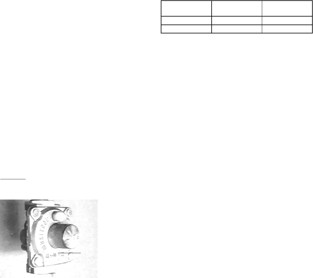
PRESSURE REGULATOR
Fig. 2 - Gas Pressure Regulator
Above 4.500 ft consult your local gas supplier.
Altitude Natural Gas Liquid Propane
inches W.C: inches W.C:
0' - 2.000 ft 5.7" 10.5"
2.000 ft - 4.500 ft 4.6" 8.5"


