


10
TROUBLE SHOOTING
Introduction
The AquaStar 38 burners are ignited by a water flow valve.
Numerous water related problems can cause this water
valve to malfunction such as: Insufficient water flow volume
to activate the burners at its minimum flow requirement;
Dirt in the water flow valve causing it to malfunction;
Sediment build-up in faucet aerators, or shower heads;
Uneven pressures between cold and hot. (with single lever
faucets) Plumbing cross overs. These water flow related
problems can cause the heater to deliver less than its full
output, or to fail to ignite or to shut down completely.
Problems are stated in upper case, bold face. Most
common causes for the problems follow in order of
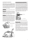
likelihood. The suggested solutions require that the cover
be taken off. To this, remove incandescent particle tray,
pull off the temperature adjustment knob and unscrew and
remove the plastic collar and unscrew the central screw
located at the bottom of the front cover. Pull main cover
out toward you and lift up and out.
1. No gas to the Aquastar
A. Gas cock on gas line may not be open.
B. Gas valve button has not been moved to “PILOT
POSITION”. Slide button to right to single flame position
( ).
2. In-line Aquastar gas regulator jammed (usually on
LP gas)
Replace or unjam the regulator. Note: The regulator
furnished with thw heater is designed for low gas pressure.
Excessive pressure will lock it up (propane only). Jamming
usually happens if the gas pressure between the gas tank
(propane) and the water heater’s gas regulator has not
been reduceed. See page 2 for recommended correct gas
pressure and check with gas service person.
3. Pilot orifice clogged and/or air screen dirty
Clogging of the pilot burner can be caused by dust and
any suspended matter contained in the ambient air.
Although the filters can lengthen the cleaning intervals,
they can never completely prevent such clogging. In
consequence the gas jet issuing from the pilot orifice is
reduced and or the air mixture is reduced. The pilot flame
is weak and thus can no longer heat the thermocouple
sufficiently. For cleaning purposes, the air filter screen is
pulled off, washed and blown out. The pilot orifice has
likewise to be cleaned or exchanged. Consult Controlled
Energy or a gas service person.
4. Air in the Gas Line
Note: Normally this is a problem only at the time of initial
installation, after the pipes have been worked on, or after
a propane tank has been allowed to empty, or after the
heater has been shut down for a long time.
Bleed all the air trapped in the gas line. Because of the
very small pilot orifice (especially on LP gas models),
bleeding out all the air could take several minutes. Slide
the gas valve button ( ) to pilot position ( ) and depress
this button until all the air has escaped, and the gas has
arrived. During this process, press on the piezo ignition
button separately until the pilot flame has ignited.
PILOT LIGHTS BUT FLAME GOES OUT WHEN
BUTTON IS RELEASED
1. Pilot push button was not pushed in far enough or
was not held in long enough
Slide the gas valve button ( ) to pilot position ( ) and
depress this button. Hold it pushed in for at least 15
seconds to give time for the pilot flame to properly heat
the tip of the thermocouple.
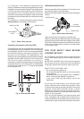
2. Pilot flame improperly aimed or is too weak so it is
not properly heating the tip of the thermocouple.
The Pilot flame should be a sharp blue flame and aimed
at the tip of the thermocouple so that it envelops 10 mm
(3/8 “) of the thermocouple tip. Pilot flame has to be properly
aimed at the thermocouple. See Fig 7.
3. Poor thermocouple connection at the
electromagnet
Note: Electromagnet is part #8707201012 located on the
right side of the gas valve behind the piezo pushbutton
assembly. Check the tightness of the thermocouple
connection nut at the electromagnet: The Electro-magnet
connection is a large aluminum 17mm hex head nut. The
thermocouple end is a 5 mm brass nut which screws into
the 17 mm nut. Tighten the thermocouple nut snugly but
not too tight.
4. Poor circuit connections at the ECO. (Energy Cut-
Off overheat protection)
Oxidation or looseness of the ECO terminal connections
can result in millivolt current loss through the thermocouple
safety circuit. Clean terminals with very fine sand paper or
an eraser and reconnect ECO leads.
5. Faulty ECO (part #8707206040)
If cleaning the terminals attached to the ECO did not fix
the problem, connect a jumper wire between the two wires
and try to relight the pilot. If the pilot flame now remains
on, replace the ECO. If the flame still goes out when the
button is released, the ECO is not defective. Go to next
step.
6. Faulty thermocouple (part #8747202083) or
electromagnet ) Unless these 2 parts are at least 8
to 10 years old, it is very unlikely that they are faulty.
Before testing, reconfirm that #2 is absolutely
correct, and that all connections are clean and tight.
To test the thermocouple, disconnect the thermocouple
lead to the ECO. Insert a multi-meter probe on the
thermocouple ECO connection and attach the other meter
lead on the spade connector of the ECO. Light the pilot
flame, and take a reading on the meter. If it reads less
than 24mv, replace the thermocouple. If the reading is
24mv or over the thermocouple is good. To test the electro-
magnet, take another reading across the ECO spade while
the pilot flame is on. The reading should drop to about 15
mv. If it does not and remains unchanged, replace the
electromagnet.