


5
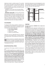
Appliances located in confined spaces:) The confined
space must be provided with two permanent openings,
one commencing within 12 inches of the top and one
commencing within 12 inches of the bottom of the
enclosure. Each opening must have a minimum free area
of one square inch per:
- 1000 Btu/hr if all air is taken from inside the building.
- 2000 Btu/hr if all air is taken from the outside by horizontal
ducts.
- 4000 Btu/hr if all air is taken from the outside by direct
openings or vertical ducts.
Louvers, grills and screens have a blocking effect. If the
effective free area is not known, increase the sizes of your
openings by 75% if your louvers are wood and by 30% if
your louvers are metal. Refer to the National Fuel Gas
Code for complete information. In buildings of tight
construction all air should be taken from outside. That
would be 2000 cubic feet for the Aquastar 38B alone.
CLEARANCES
The Aquastar 38 B is design certified for installation on a
combustible wall and for installation in an alcove or closet
with the minimum clearances to combustible and non -
combustible construction listed below
A. Top 12 inches ( 305 mm)
B. Front 4 inches (102mm)
C. Back 0 inches
D. Sides 4 inch (102mm)
E. Bottom 12 inches (306 mm)
Clearance from vent is dependent upon the clearance
rating of the venting material used. For example: type B-1
vent is approved for 1 inch clearance, B-2 vent for 2 inch,
etc.
Note: Minimum clearance to combustible materials should
not be less than 6" for single wall flue pipe. Note that this
clearance can be reduced if combustible material are
protected as per table VI of the National fuel Gas Code or
if Type B gas vent is used.
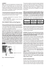
MOUNTING INSTALLATION
The Aquastar 38 B is design certified for mounting on a
wall.
Do not install this appliance on a carpeted wall or over
floor covering which is combustible, such as carpet. The
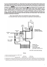
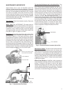
heater must be mounted on a wall using appropriate
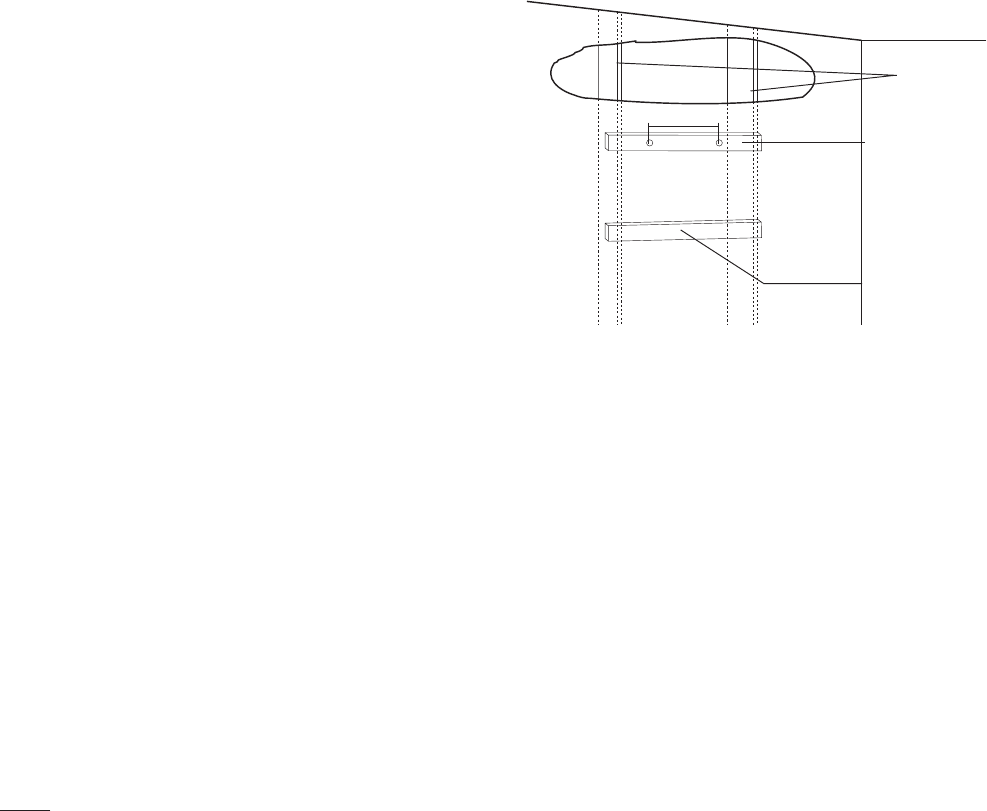
anchoring materials. If wall is a stud wall sheathed with
plasterboard, it is recommended that support board(s),
either 1x4’s or 1/2" (minimum) plywood first be
attached across a pair of studs and then the heater
should be attached to the support boards. See Fig 1.
Expansion and contraction of piping due to changing water
temperature in the pipes imparts movement to the heater
which, if mounted directly to a brittle, friable board, such
as plasterboard, can cause failure of mounting.
Before installing the unit, be certain you have the correct
heater for your type of Gas – Propane or Natural Gas.
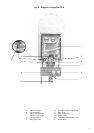
Fig. 1 - Mounting the Heater
Identification labels are found on the shipping box, and on
the rating plate which is located on the right side panel of
the cover. Also, each burner orifice is stamped with a num-
ber (79 for LPG and 120 for Natural Gas).
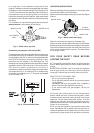
VENTING
Vent pipe connection. WARNING: Do not reduce the
vent pipe size.
This appliance must be vented to the outside following all
local ordinances and specifications for installing a gas
appliance vent or chimney. The venting system must be
designed and constructed so as to develop a positive flow
adequate to remove flue gasses to the outdoors. Minimum
vent size must be 4". Minimum height must be 6 feet,
provided there are no elbows. Termination of vent
must be 2 feet above any obstruction within a 10 foot
radius. Consult your gas utility or National Fuel Gas
Code if vent will have elbows or share venting with
another appliance. The vent connector should have
as much vertical rise as possible (minimum 12”) before
any horizontal run. The appliance must be located as
close as practicable to a chimney or vent. The vent pipe
sections must be secured to each other with sheet metal
screws. Keep in mind the minimum clearance from the
top of your heater. Remember also that single wall vent
pipe connectors require a 6 inch clearance from
combustibles. National Fuel Gas Code specifies double
wall — Type “B” — vent pipe be used in cold climates and
for gas vents running through attics. We consider double
wall vent pipe preferable in all circumstances. Any vent
section greater than 45 degrees from vertical is considered
horizontal. Horizontal sections of vent connectors must
slope upwards at least 1/4 inch for every foot of its
horizontal length. Keep the horizontal section short and
avoid too many elbows.
WALL STUDS
1” X 4”
SPACE BOARD
SUPPORT BOARD
5 ½”