


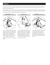
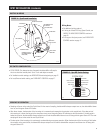
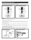
FIGURE 6 – Drain Trap
90-961
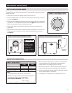
MECHANICAL INSTALLATION (CONTINUED)
DRAIN
1. Adjust feet of dehumidifier to allow a 2-1/2” minimum clearance
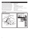
for drain trap. See Figure 6. Use the 90° elbow if necessary for
clearance restrictions. See Figure 7.
2. Use PVC primer and cement for drain assembly to the dehumidifier
drain outlet.
3. Complete assembly by piping the 3/4” PVC trap to a drain or
condensate pump. Make sure the drain line has a constant
downward slope and is not kinked.
4. To prime the drain trap and to verify the drain line is not blocked,
slowly pour a pint of water into the dehumidifier drip pan located
below the coil.
CAUTION
1. Drain trap must be primed with water before use.
2. A condensate pan with a float switch is required in attic
installations.
High Side
Low Side
Drain Outlet
Drain Trap
2-1/2
Arrows on
trap show
water flow
direction
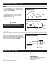
FIGURE 7 – Drain Trap with 90° Elbow
90-961
High Side Low Side
Drain Trap
90° PVC Elbow
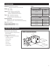
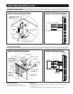
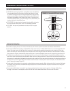
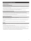
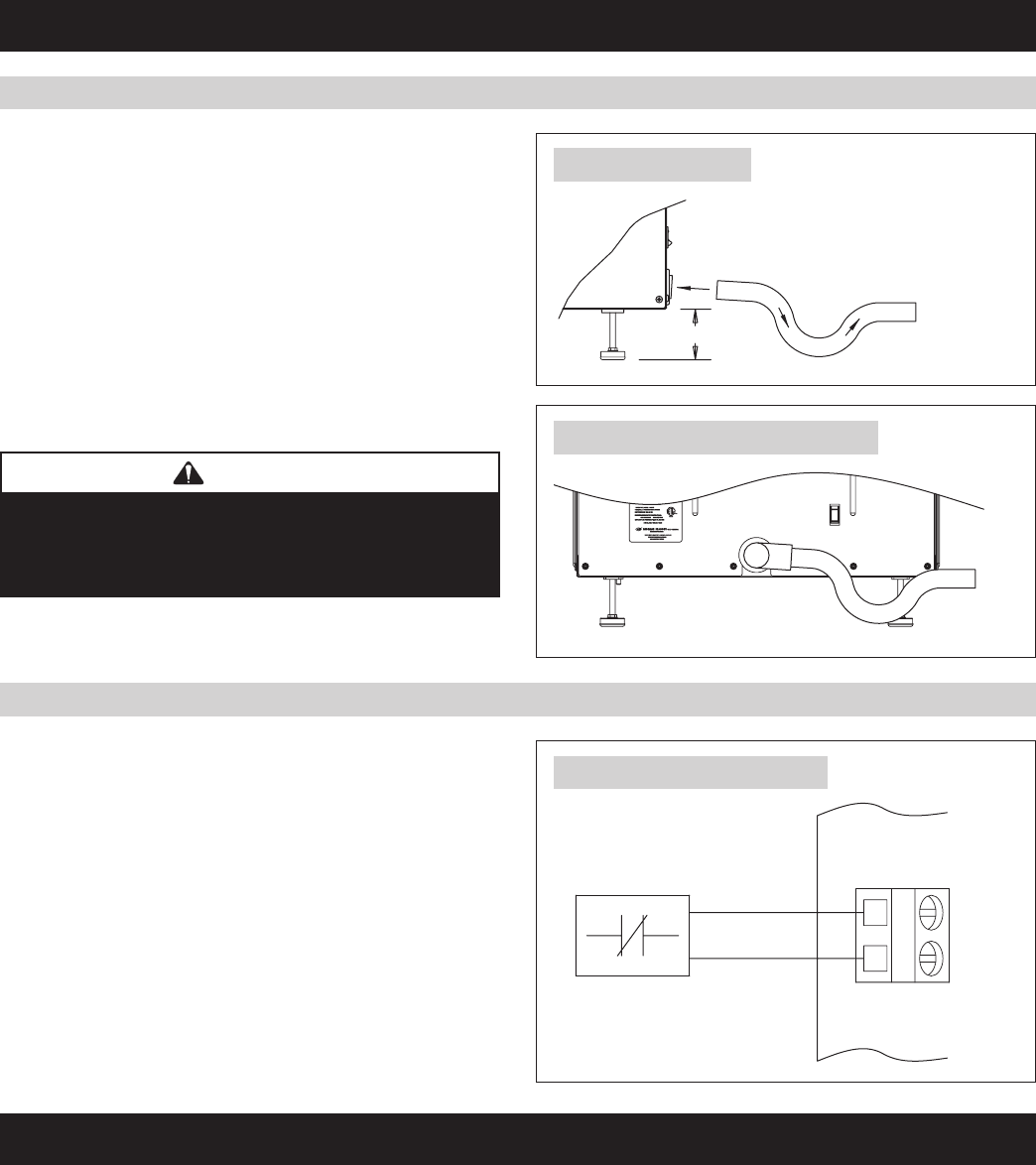
FIGURE 8 – Float Switch Wiring
If the dehumidifier is installed in an attic or another location requiring
leak protection, the unit should be placed in a condensate pan with
a normally closed, condensate overflow safety switch (float switch).
Remove the jumper from the float switch terminals on the control board
and wire the float switch to the terminals. See Figure 8.
FLOAT
SWITCH
LOW VOLTAGE NORMALLY
CLOSED FLOAT SWITCH
90-1429
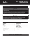
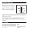
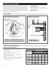
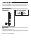
This installation is used when the HVAC equipment conditions the whole home.
Using the dehumidifier in conjunction with the HVAC system is the optimum solution
for year-round, whole-home control. This installation is typically in basement or attic
locations. Ducting the unit to the return and supply, where air is pulled from the
return duct, dehumidified, and discharged to the supply duct, is the most common
setup. Additional configurations include only ducting the dehumidifier outlet to the
supply or ducting the inlet and outlet to the return duct. In the latter case, the HVAC
fan must be activated during dehumidification.
Required Components
Duct Work
18 – 22 AWG Wire
Optional Components
Condensate Pan & Normally Closed Float Switch
Model 70 Living Space Control
Third-Party Control
WHOLE-HOME INSTALLATION
FLOAT SWITCH
6