MODEL 70 LIVING SPACE CONTROL
WIRING & DIP SWITCH CONFIGURATION
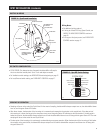
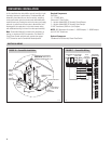
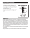
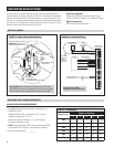
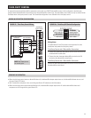
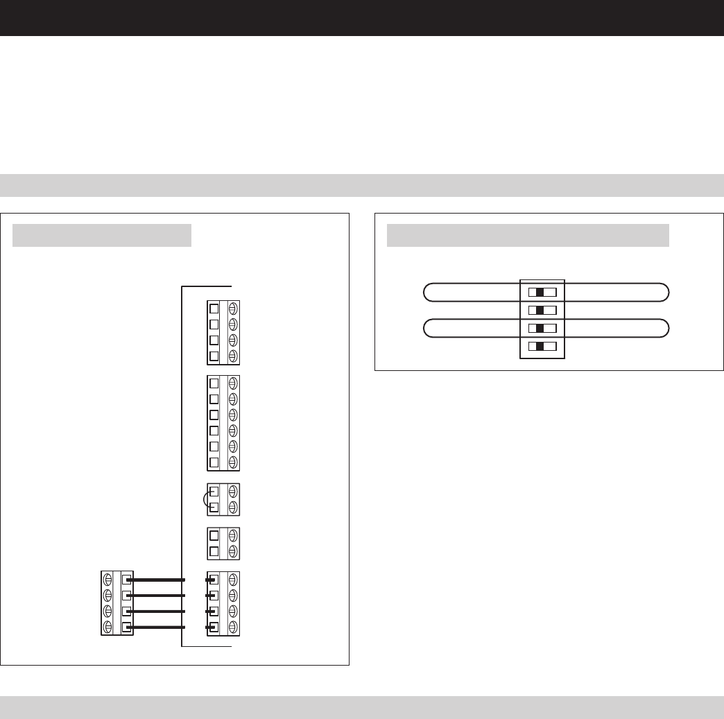
TheModel70LivingSpaceControlcontainsitsownsensorsthatoverridethemaincontrolsensorsonthedehumidifier.Thepurposeofutilizing
the Model 70 is to have the dehumidifier control located in a living area, where the homeowner can monitor and control humidity levels. Once
connectedandpowered,theModel70isautomaticallyrecognizedbythedehumidifierandwillcontinuouslycommunicatetheairconditions
and the dew point setting to the dehumidifier control. No sampling is needed when using a Model 70 because the control is located in the
space to be conditioned and is measuring the dew point in that space. Refer to the Model 70 Installation Instructions for location and mounting
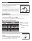
instructions. The Convertible configuration is not available with the Model 70 Living Space Control.
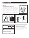
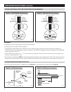
FIGURE 26 – Model 70 DIP Switch Configuration
90-1538
LOCAL
CONVERTIBLE
EXTERNAL
SYSTEM SETUP
HVAC FAN ON
VENT-TIMED
VENT-AUTO
WHL HOUSE
HVAC FAN OFF
ON
1 2 3 4
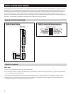
90-1537
A +BDEH
REMOTEHVAC EQUIP
VENT
Cf
Gs Gh W -DHRf
DAMPERS
-
B
+
A
SENSOR
ODT
FLOAT
SWITCH
DEHUMIDIFIER
CONTROL BOARD
MODEL 70
SEQUENCE OF OPERATION
Whole-Home
•Thereisa6minutedelayuponpoweruporaftercyclingpower.
•IfthedewpointoftheairisabovethedewpointsettingontheModel70,thedehumidifierdamperoutputturnson,thedehumidifierblower
turns on, and the green Status LED flashes.
•Threesecondsafterthedehumidifierblowerturnson,thecompressorturnson,andthegreenStatusLEDswitchestosolidillumination.
•WhenthedewpointfallsbelowthedewpointsettingontheModel70,thedehumidifierdamperoutputturnsoffandthedehumidifier
compressor and blower turn off along with the green Status LED.
FIGURE 25 – Model 70 Wiring
16


