


VENTILATION OR AIR CYCLING (CONTINUED)
DETERMINE FRESH AIR DELIVERY RATE
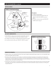
1. Measure the negative static pressure of the return system at the location where the outdoor air duct enters the return duct.
2. See Table 4 for estimated inlet airflow in CFM, based on duct type, length, and available negative pressure. Use an airflow measuring device
for a more accurate airflow delivery rate.
3. Record the Delivered CFM. __________
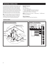
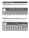
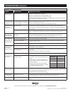
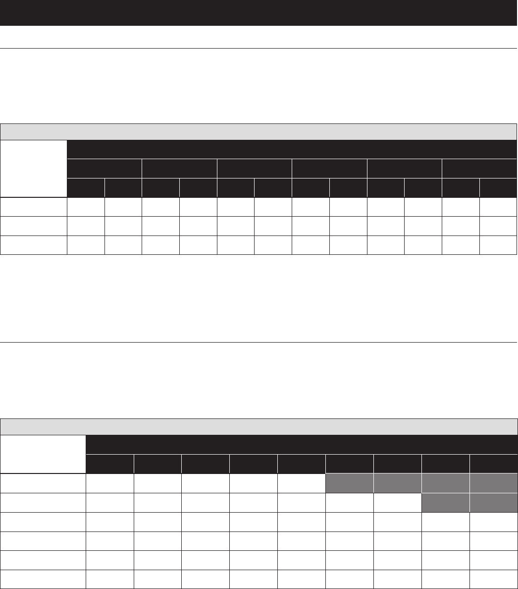
TABLE 4 – CFM Delivered
Duct Length
Negative Static Pressure (“w.c.) as Measured for Return Duct or Plenum
0.05 0.1 0.15 0.2 0.25 0.3
Flex Pipe Flex Pipe Flex Pipe Flex Pipe Flex Pipe Flex Pipe
10 ft.
60 65 85 90 105 110 120 125 135 140 150 160
20 ft.
55 60 80 85 100 105 115 120 130 135 140 150
30 ft.
50 55 75 80 95 100 110 115 125 130 130 140
Note: For the table above, 6” flex duct is laid loose with two, wide 90° bends and a fully opened damper. Rigid pipe values are based on 6” duct,
two 90° elbows, and a fully open damper. In both cases, the air intake is through a metal vent hood with inlet screen. Airflow may need to be
adjusted up or down for variations in duct work.
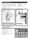
DETERMINE CYCLE TIME
1. Use the Required CFM and Delivered CFM from the above steps to determine the Cycle Time from Table 5.
2. The values are listed for a 1 hour Cycle Period. For a 2 hour Cycle Period, set the Cycle Time to twice the values listed in Table 5.
3. The values highlighted in gray cannot be set due to the maximum 60 minute Cycle Time. A second ventilation device (i.e., bigger duct or
second duct) will be required to meet ventilation needs.
TABLE 5 – Cycle Time Setting (minutes) for Airflow Delivered vs. Airflow Required for 1 hour Cycle
CFM Delivered
CFM Required
20 30 40 50 60 70 80 90 100
60
20 30 40 50 60
70 80 90 100
80
15 25 30 40 45 55 60
70 75
100
15 20 25 30 35 40 50 55 60
120
10 15 20 25 30 35 40 45 50
140
10 15 15 20 25 30 35 40 45
160
10 10 15 20 25 25 30 35 40
13