


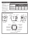
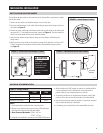
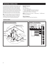
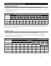
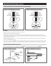
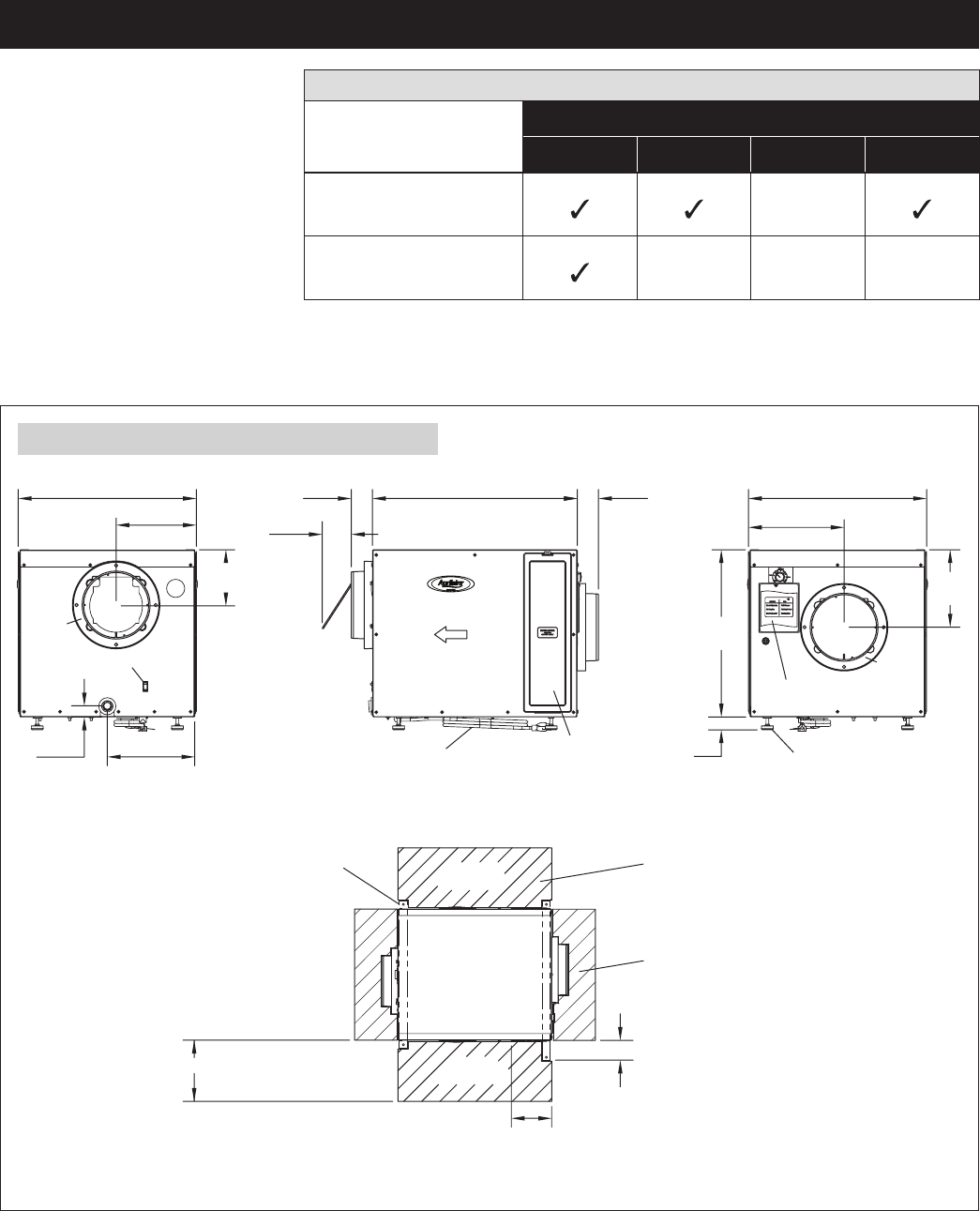
FIGURE 2 – Dimensions and Location Considerations
20-3/4
(527)
24.00
(610)
9-1/2
(241)
10-3/8
(264)
1-1/4
(32)
6-1/2
(165)
OFF
ON
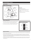
Air Outlet
8 in.
Round
Collar
OFF/ON Switch
Drain
2-1/2
(64)
3-7/8
(98)
Damper
Fully Open
Filter Access
(Front and Back)
Power Cord
Air Flow
2-1/2
(64)
20-3/4
(527)
11
(279)
9
(229)
19-5/8
(498)
3
(76)
Max.
Wiring
Access
Adjustable Legs
OUTLET AIR END FRONT VIEW INLET AIR END
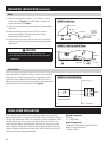
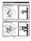
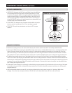
SUSPENDING AND SERVICE CLEARANCE
SERVICE
CLEARANCE
SERVICE
CLEARANCE
TOP VIEW
OF UNIT
THERE MUST BE AT LEAST
20 IN. (508mm) OF CLEARANCE
ON EITHER SIDE FOR
FILTER REMOVAL
THERE MUST BE AT LEAST
12 IN. (305mm) OF CLEARANCE
ON BOTH ENDS FOR
CONTROL SETTINGS
IF SUSPENDING THE UNIT, USE
TWO STRUTS TO SUPPORT THE
BASE ON THE OUTSIDE EDGES
OF THE FEET LOCATIONS.
Two Support Struts
for Suspending
(Bottom of Unit)
3 in. (76mm) Minimum Clearance
for Filter and Front Panel
Removal (either side)
20 in. (508mm) Minimum Clearance
for Filter and Front Panel
Removal (either side)
6 in. (152mm) Minimum Clearance
for Filter and Front Panel
Removal (either side)
Air Inlet
8 in.
Round
Collar
90-1545
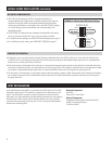
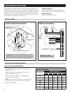
TABLE 1 – Location Notes
Requirement
Application Location
Attic Garage Basement Crawl Space
All ductwork must be
insulated and sealed.
Drain pan with overflow
protection placed under unit.
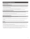
LOCATION CONSIDERATIONS
1. Install Unit Indoors: Do not expose
to elements.
2. Drain Accessibility: A condensate
pump may be required if a drain is not
located in the installation area.
3. Power: Outlet within 8 ft. of unit.
4. Filter Access: Allow for 20” of
clearance on one side of unit for
removal of filter (see Figure 2).
5. Inlet: Allow for 12” of clearance to
access control and control door/wiring
access (see Figure 2).
4