


7
BETWEEN THE RELIEF VALVE AND TANK. DO NOT PLUG THE
RELIEF VALVE.
The drain line connected to this valve must not contain a reducing
coupling or other restriction and must terminate near a suitable
drain to prevent water damage during valve operation. The
discharge line shall be installed in a manner to allow complete
drainage of both the valve and line.
DO NOT THREAD, PLUG OR
CAP THE END OF THE DRAIN LINE.
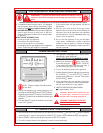
VENTING
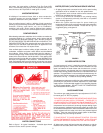
WARNING
NEVER OPERATE THE HEATER UNLESS IT IS VENTED TO
THE OUTDOORS AND HAS ADEQUATE AIR SUPPLY TO AVOID
RISKS OF IMPROPER OPERATION, FIRE, EXPLOSION OR
ASPHYXIATION.
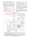
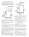
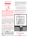
VENT PIPE TERMINATION
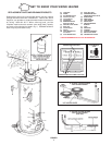
The first step is to determine where the vent pipe will terminate.
See Figures 3, 8 and 9. The vent may terminate through the roof
as shown in Figure 9 or through a sidewall as shown in Figure
8.
IMPORTANT
The vent system must terminate so that proper clearances are
maintained as cited in local codes or the latest edition of the
National Fuel Gas Code, ANSI Z223.1, 7.3.4e and 7.8a, b.
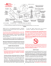
For your convenience instructions on proper installation through
a sidewall are provided in Figure 3 and the numbered points
below:
1. The exit terminals of a mechanical vent system shall be not
less than 7 feet above grade when located adjacent to public
walkways.
2. A venting system shall terminate at least 3 feet above any
forced air inlet located within 10 feet.
3. The venting system shall terminate at least 4 feet below, 4
feet horizontally from or, 1 foot above any door, window or
gravity air inlet into any building.
4. The manufacturer also recommends that the vent system
termination not be installed closer than 3 feet from an inside
corner of an L shaped structure and not be less than 1 foot
above grade. The vent shall terminate a minimum of 12''
above expected snowfall level to prevent blockage of vent
termination.
5. The vent termination shall not be mounted directly above or
within 3 feet horizontally from an oil tank vent or gas meter to
avoid potential freeze-up from condensation.
Plan the vent system layout so that proper clearances are
maintained from plumbing and wiring.
Vent pipes serving power vented appliances are classified by
building codes as "vent connectors". Required clearances from
combustible materials must be provided in accordance with
information in this manual under LOCATION OF HEATER and
INSTALLATION OF VENT SYSTEM, and with the National Fuel
Gas Code and local codes.
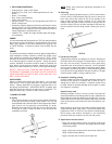
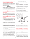
PLANNING THE VENT SYSTEM
Plan the route of the vent system from the discharge of the blower
to the planned location of the vent terminal.
1. Layout the total vent system to use a minimum of vent pipe
and elbows. Take into consideration that an elbow will be
necessary to make the first vent pipe connection to the power
venter outlet (see Figure 6).
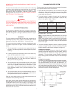
2. This water heater is capable of venting the flue gases the
equivalent of thirty (30) feet of 3 inch pipe or eighty-five (85)
feet of 4 inch pipe as listed in Table 1.
TABLE 1
Number of 3" Maximum 4" Maximum
90° Elbows Pipe (Feet) Pipe Feet
ONE (1) 25 77
TWO (2) 20 69
THREE(3) 15 61
FOUR (4) 10 53
FIVE (5) - - - 45
Minimum of 7 equivalent feet (one {1} elbow and 2 feet) must
be installed for 3" and 4" pipe.
NOTE: The equivalent feet of pipe listed above are exclusive
of the "45° Elbow" termination. That is, the termination "45°
Elbow", with installed screen, is assumed to be in the system
and the remainder of the system must not exceed the thirty
(30) equivalent feet of 3 inch pipe or eighty five (85) equivalent
feet of 4 inch pipe.
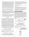
3. The blower discharge adapter is made to accept only straight
sections of 3" pipe. To start a minimum of 2 inches of 3" pipe
must be attached to the blower discharge (See figure 6).
If using 3 inch vent pipe:
A minimum of 2 inches, maximum of 4 feet of 3" pipe must be
attached to the blower before the first 3-inch elbow. After the
first elbow add the additional venting required for the
installation. The total system cannot exceed 30 equivalent
feet of venting, where each elbow is equal to 5 feet of straight
pipe.
If using 4 inch vent pipe:
Two inches of 3" pipe must be attached to the blower discharge.
A 4" x 3" reducer is added and then up to maximum 4 feet of 4
inch pipe added before the first elbow. An additional 4" x 3"
reducer and (1) foot of 3" pipe must be added to the end of the
vent system before terminating into the 3" 45° elbow. The total
system cannot exceed 85 equivalent feet of 4" venting, where
each elbow is equal to 8 feet of straight pipe.
FIGURE 4