


40
• Soft Fault State: (See "Fault Description" section for list of soft
and Auto Reset faults.)
The CCB turns off the Powered Vent and the IRI Gas. The pump
remains on for the selected post-circulate time to cycle the hot
water out of the boiler. The FCB's are commanded to shut down
and the Alarm output is turned on. The green LED turns off and
the red "Service" turns on. The CCB remains in this state until
one of the following occurs:
• One hour passes (automatic restart after one hour)
• If Communications error system will automatically
restart if communications re-establishes.
• If user presses Select key while current error screen is
displayed (Hard reset).
• If high-limit error - the outlet temperature drops below the high
limit trip point minus the high limit differential. (outlet water
temperature drops to safe level). The fault is logged in the
error history when the fault state is exited.
• Hard Fault State: (See "Fault Description" section for list of
soft and Auto Reset faults.) The CCB turns off the Powered
Vent and the IRI Gas. The pump remains on for the selected
post-circulate time to cycle the hot water out of the boiler. The
FCB's are commanded to shut down and the Alarm output is
turned on. The green LED turns off and the red "Service"
turns on and off (flashes). The only way to exit this state is for
the user to press the Select key while the current error screen
is displayed. The fault is logged in the error history when the
fault state is exited.
While the CCB is in the Heating mode the activated FCB stage
moves from Idle, to Pre-Purge, to Heat Igniter, to Check for Flame,
and then to Heating. The process waits in this state until the call for
heat is satisfied, the thermostat input is opened, or a fault occurs.
When heat is satisfied, the sequence continues to Post-Purge and
then back to Idle. If three tries for ignition has been selected on the
CCB dipswitch and flame is not detected at the appropriate time,
then the sequence moves to the Inter-Purge state for 15 seconds
and the FCB heat sequence is repeated. If flame is still not detected
after the third try the process declares a fault, jumps out of sequence
and goes to the error state. Other types of faults detected at any
time will also cause a jump to the error state.
Description of FCB control states:
• Idle State:
When any error is declared during idle state-The system will
remain in this state until the CCB request a heating cycle, or a
cold purge.
• Pre-Purge State:
If the stage does not have a blower, this state is skipped and the
system advances to the Heat Igniter State. Otherwise the Blower
is turned on. After 10 to 34 seconds (34 seconds for cold
purging) the system switches to the Heat Igniter State.
• Heat Igniter State:
The sequence of operation is as follows: "The igniter relay is
energized and the heat up period begins. After 18-20 seconds,
if the igniter has reached a minimum of 2.8 amps, the gas valve
safety circuit is then activated. If in this amount of time, the igniter
fails to reach a minimum amp draw of 2.8 amps, the unit will re-
cycle up to 3 times before locking out on igniter hardware failure.
If the igniter does reach the minimum required amp draw of 2.8
amps, the gas valve circuit is energized, and the system
advances to Flame Check status.
• Check for Flame State:
The gas valve is turned on. After 1.5 seconds, the system checks
that the gas valve relay is on. If it is not, the ignition trial is
considered to have failed and the system advances to the Inter-
Purge state, if any ignition trials remain, otherwise an error is
declared.
The flame sensor is checked. If flame is detected, the igniter is
turned off. The state machine then advances to the Heating
State. If after 5 seconds, the flame is still not sensed then the
ignition trial is considered to have failed. The state machine
advances to Inter-Purge if any ignition trials remain, otherwise
an error is declared.
• Heating State:
The system remains in this state until the call for heat is cancelled
or a fault occurs. The system returns to the Idle state if the call
for heat is cancelled, or satisfied and to the appropriate fault
state if a fault occur.
• Inter-Purge State:
The gas valve and the igniter are turned off. The blower is on.
After approximately 15 seconds the system goes back to the
Heating Igniter State.
• Post-Purge State
The gas valve and the igniter are turned off. If this stage does
not have a blower the system returns to the idle state. If it does
have a blower then the blower is left on. After approximately 25
seconds, the system returns to the Idle state.
• Error State
The gas valve and the igniter are turned off. The FCB micro tells
the CCB micro which error has occurred. The system waits in
this state until the CCB sends a command to clear the error, and
the system returns to the idle state.
• Cold Purge State
Cold purge occurs when the CCB micro commands all blowers
to go on before lighting the first stage to clear the unit of residual
gases. This state normally lasts approximately 32 seconds but
on a special situation can last up to 5 minutes. If on the first call
for heat after power up, blower prover switch is open, this state
will take up to 5 minutes before declaring an error. This special
mode is used by service technicians to adjust the blower shutter.
The CCB will wait the normal cold purge time (normally 32
seconds) before checking for activation of all active blower prover.
If blower prover is active at this time the CCB cancels the cold
purge request. After the first cold purge has been done a flag is
set to prevent further activation of the shutter adjust 5 min. delay.
Any further requests for cold purge will last the normal cold
purge time. The FCB will go into fault mode if the blower prover
does not activate after 15 seconds. This time allows the blower
relay to activate, the blower to come up to speed, and the
response from the blower prover to be filtered.
• User Settings Screen:
Each setpoint or user setting has either a limited selection of
values, or a limited range of values. The Up/Down keys are
used to change values. After changing an item, the Select key is
pressed to accept the change, or the Menu key is pressed to
reject the change and restore the item to its original value. The
following setpoints can be changed:
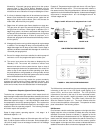
• Operating Setpoint:
This setpoint sets the base temperature for the control algorithm.
See Figures 20A & 20B.