


10
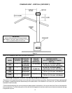
POWER VENT (OPTIONAL)
The length of vent used in horizontally vented installations can be
extended beyond the lengths shown in Tables 11 and 13 by
implementing the kits listed below:
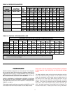
TABLE 9: POWER VENT KITS.
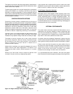
CONNECTING BOILER TO A COMMON VENT
Do not connect the boiler to a common vent or chimney with solid
fuel burning equipment. This practice is prohibited by most local
building codes as is the practice of venting gas fired equipment to
the duct work of ventilation systems.
Where a separate vent connection is not available and the vent
pipe from the boiler must be connected to a common vent with an
oil burning furnace, the vent pipe should enter the common vent or
chimney at a point ABOVE the flue pipe from the oil furnace.
UL/ULC listed double wall type B-1 gas vents, through 16" diameter,
can be installed in heated and unheated areas and can pass
through floors, ceilings, partitions, walls and roofs, provided the
required clearance is observed.
At the time of removal of an existing boiler, the following steps shall
be followed with each appliance remaining connected to the
common venting system. Perform these steps while the other
appliances remaining connected to the common venting system
are not in operation.
1. Seal any unused opening in the common venting system.
2. Visually inspect the venting system for proper size and horizontal
pitch and determine there is no blockage or restriction, leakage,
corrosion or other unsafe condition.
3. Insofar as is practical, close all building doors, windows and
all doors between the space in which the appliances remaining
connected to the common venting system are located and other
spaces of the building. Turn on clothes dryers and any
appliance not connected to the common venting system. Turn
on any exhaust fans, such as range hoods and bathroom
exhausts, so they will operate at maximum speed. Do not
operate a summer exhaust fan. Close fireplace dampers.
4. Test fire the appliance(s) being inspected, making sure to follow
the manufacturers lighting and operating instructions.
Appliance(s) operating controls should be adjusted to provide
continuous service.
5. Check vent pressure of the appliance 24 inches (61.0 cm) above
boiler vent collar. Vent pressure should be maintained between
-0.02" W. C. and -0.04" W.C. to assure proper operation. For
appliances with a draft hood, check for spillage with mirror,
smoke or other device five minutes after placing appliance in
operation.
6. After it has been determined that each appliance remaining
connected to the common venting system properly vents when
tested as outlined above, return doors, windows, exhaust fans,
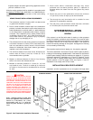
the exhaust vent pipe must be listed for use with category III gas
burning heaters such as "Saf-T-Vent" manufactured by Heat-Fab
Inc. This vent system must be 100% sealed with a condensate
trap located as close to the boiler as possible. When sizing exhaust
piping and intake air piping, 90-degree elbows are equivalent to 10
feet (3.1 m) of straight pipe and 45-degree elbows are equal to 5
feet (1.5 m) of straight pipe.
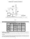
The intake air piping can be PVC, CPVC, ABS, Galvanized steel or
any suitable intake air piping that can be sealed. See Table 8 for
Direct Vent Kit numbers.
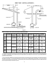
TABLE 8: DIRECT VENT KITS.
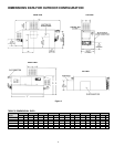
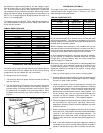
HORIZONTAL VENT INSTALLATION
This boiler can be vented through the rear of the cabinet with the
use of the fluebox and vent adaptor. Any of the previous venting
configurations can be installed with rear connections.
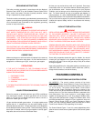
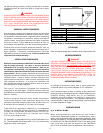
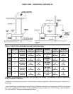
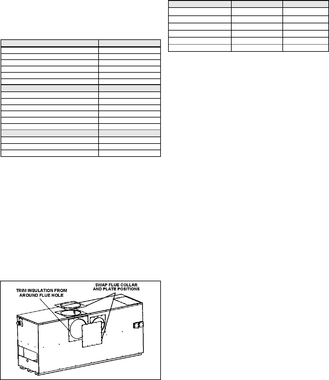
To change the unit to rear exhaust:
1. The vent collar and cover plates must be removed from the top
and rear of the unit.
2. Trim the insulation from around the rear flue hole in the jacket
and the fluebox. Support insulation from inside the fluebox to
facilitate cutting. Use safety precautions such as gloves. Place
the gasket and vent adaptor in the horizontal position. Place
the gasket and flue plate in the vertical position as shown in
Figure 4.
Figure 4. Switching from Vertical to Horizontal Venting.
POWER VENT KIT NO. MODEL MAX. LENGTH
211499 G(B,W) 1000 110' (33.5 m)
211499-1 G(B,W) 1300 100' (30.5 m)
211499-1 G(B,W) 1500 100' (30.5 m)
211499-2 G(B,W) 1850 100' (30.5 m)
211499-3 G(B,W) 2100 100' (30.5 m)
211499-4 G(B,W) 2500 100' (30.5 m)
HORIZONTAL DIRECT VENT KIT NO. MODEL
211090 G(B,W) 1000
211090-1 G(B,W) 1300
211090-1 G(B,W) 1500
211090-4 G(B,W) 1850
211090-2 G(B,W) 2100
211090-3 G(B,W) 2500
VERTICAL DIRECT VENT KIT NO. MODEL
211089 G(B,W) 1000
211089-1 G(B,W) 1300
211089-1 G(B,W) 1500
211089-4 G(B,W) 1850
211089-2 G(B,W) 2100
211089-3 G(B,W) 2500
AIR INTAKE TERMINAL MODEL
191965-2 G(B/W) 1000
211336 G(B/W) 1300,1500,1850
211336-1 G(B/W) 2100, 2500