


35
required): The CCB accepts analog temperature inputs from up
to three sensors (inlet, outlet and tank).
• ECO input (CCB - required):
The ECO (energy cut off) is a hi-limit switch, which is located
inside the outlet probe. It is a normally closed switch that opens
if the probe is exposed to a temperature higher than the trip
point. Once tripped, control system needs manual reset.
• Thermostat input (CCB - optional):
This input is set up to work with an externally connected
thermostat that provides a contact closure. If this input is closed
and everything else is in the proper state, a "call for heat"
condition will be initiated. These leads should be shorted
together, when a thermostat is not being used. If it is desired
that the thermostat control the temperature of the boiler, the
operating setpoint of the system should be set higher than the
temperature that the thermostat is controlling to. This will allow
the thermostat to control the boiler. When the thermostat closes,
a call for heat will be generated until the thermostat determines
that the required temperature has been reached.
Air Pressure Sensors (open condition indicates fault):
• Blocked Flue (CCB - required):
Normally closed switch that opens if the flue becomes blocked
during operation.
• Powered Vent (CCB - optional):
Normally open switch that closes when the powered vent is
operating properly. This input is enabled/disabled by a dipswitch
on the CCB.
• Blower Prover (CCB/FCB - required on Stages with Blowers).
Normally open switch that closes when the air pressure
produced by the blower is above the set point.
Gas Pressure Sensors (open condition indicates fault):
• Low Gas (CCB - required):
Normally open switch that closes when the gas pressure rises
above the trip level. This input is enabled/disabled by a dipswitch
on the CCB.
• Hi Gas (FCB - optional):
Normally closed switch that opens if the gas pressure exceeds
a set value. This input is enabled/disabled by a dipswitch on the
CCB and FCB's.
Water Level Sensor (open condition indicates fault):
• Low Water Cut Off (CCB - optional):
Normally open switch that closes when water reaches preset
level. This input is enabled-disabled by a dipswitch on the CCB.
Water Flow Sensor:
• Flow (CCB - required):
Normally open switch that closes when flow exceeds a set value.
IRI Gas Valve Sensor:
• IRI Gas Valve (CCB - optional):
Normally open switch that closes when the IRI Gas Valve is
operating correctly. This input is enabled/disabled by a dipswitch
on the CCB.
• Flame Sensor:
Flame (CCB - required).
Returns a signal to the microprocessor if flame is detected on
the burner. If the flame rod is missing or shorted, the flame will
not be detected. This input is enabled/disabled by a dipswitch
on the FCB.
Outputs from CCB and FCB's:
Relay Contact Output:
• IRI Gas Valve (CCB - 120 vac - optional):
Provides electrical power to operate an IRI Gas Valve Device.
• Alarm (CCB - 24vac - optional):
Provides electrical power to operate an external alarm. This
can be an audio device (i.e. Sonalert), a visual device (lamp),
or any other device that will operate with the voltage and current
level provided.
• Pump (CCB - 120vac - required on systems that do not have
an external pump):
Provides electrical power to directly operate a pump or the coil
of an externally connected contactor.
• Powered Vent (CCB - 24 vac - optional):
Provides electrical power to operate a powered vent.
• Blower (CCB / FCB - 120vac - required).
Single speed blowers utilize the high blower output only. Dip
switches on the FCB's enable/disable the use of blowers on
stages 2, 3 and 4.
• Igniter (FCB - 120vac - required).
Provides power to operate the HSI igniters. Dip switches on
the FCB's enables/disables the use of HSI igniters on stages
2, 3 and 4.
• Gas Valve (FCB - 24vac - required):
Provides power to activate the gas valve. The gas valve cannot
be activated when the ECO contacts are open.
• Low Water Cut Off (CCB - 24vac - optional)
Directly connected to the 24 vac line to provide power to operate
an external LWCO device.
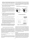
CCB/FCB Indicator Lamps & Fuses
A green LED is mounted on the PDB to indicate when line voltage
is applied. (The PDB also contain a yellow and red LED, and a
test/run jumper, that are used during installation to verify proper
power connections.) A red LED on the CCB is used to indicate
when the 24vac input fuse has blown. The FCB's also have fuses
on their 24vac power line.
Yellow LED's are located near the micros on the CCB and
FCB's. These LED's are "heartbeat indicators" and blink
approximately twice per second to indicate that the micros are
running.
CCB/FCB Jumpers:
The CCB has two jumpers and the FCB has one. JP1 on the
CCB is used to terminate the external communications line. It
is normally left off and installed when the external cable is very
long. JP2 on the CCB and JP1 on the FCB, are for factory use
only.
Igniters
The EMC 5000 system operates with Silicon Carbide Igniters.