


4
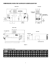
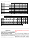
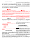
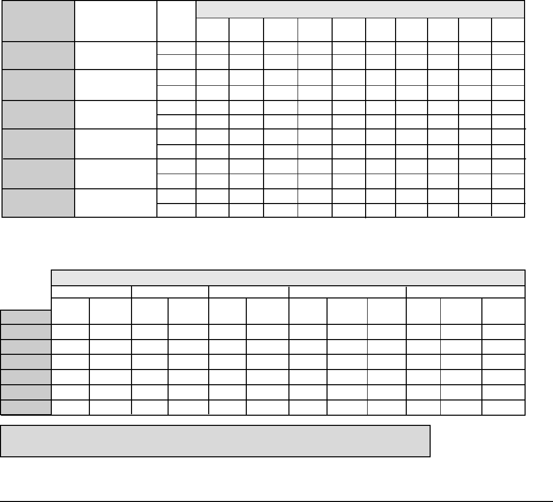
TABLE 5: PUMPING PERFORMANCE GUIDE
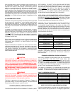
TABLE 4: RECOVERY CAPACITIES
TEMPERATURE RISE - DEGREES °F (°C)
Input Rating Water 40°F 50°F 60°F 70°F 80°F 90°F 100°F 110°F 120°F 130°F
MODEL BTU/Hr. (kW) Flow (22.2°) (27.7°) (33.3°) (38.8°) (44.4°) (50°) (55.5°) (61.1°) (66.7°) (72.2°)
GW - 1000 990,000 (290.1) GPH 2520 2016 1680 1440 1260 1120 1008 916 840 775
LPH 9526 7620 6350 5443 4763 4234 3810 3462 3175 2930
GW - 1300 1,300,000 (380.9) GPH 3309 2647 2206 1891 1655 1471 1324 1203 1103 1018
LPH 12508 10006 8339 7148 6256 5560 5005 4547 4169 3848
GW - 1500 1,500,000 (439.5) GPH 3818 3055 2545 2182 1909 1697 1527 1388 1273 1175
LPH 14432 11548 9620 8248 7216 6415 5772 5247 4812 4442
GW - 1850 1,850,000 (542.0) GPH 4709 3767 3139 2691 2355 2093 1884 1712 1570 1449
LPH 17800 14239 11865 10172 8902 7912 7122 6471 5935 5477
GW - 2100 2,100,000 (615.3) GPH 5345 4276 3564 3055 2673 2376 2138 1944 1782 1645
LPH 20204 16163 13472 11548 10104 8981 8082 7348 6736 6218
GW - 2500 2,490,000 (729.6) GPH 6338 5071 4225 3622 3169 2817 2535 2305 2113 1950
LPH 23958 19168 15971 13691 11979 10648 9582 8713 7987 7371
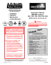
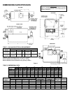
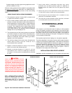
FOREWORD
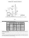
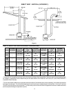
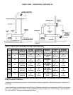
Detailed installation diagrams are in this manual. These diagrams
will provide the installer with a reference of materials needed and a
suggested method of piping. IT IS NECESSARY THAT ALL WATER
AND GAS PIPING, AND THE ELECTRICAL WIRING BE INSTALLED
AND CONNECTED AS SHOWN IN THE DIAGRAMS.
CHECK DIAGRAMS THOROUGHLY BEFORE STARTING
INSTALLATION TO AVOID POSSIBLE ERRORS AND MINIMIZE
TIME AND MATERIALS COST. SEE FIGURES 1 THROUGH 5 AND
TABLES 1, 2, AND 3.
This design complies with the current edition of ANSI Z21.13-CSA
4.9 for Gas-Fired Low-Pressure Steam and Hot Water Boilers.
MAKE SURE THE GAS ON WHICH THE BOILER WILL OPERATE
IS THE SAME AS THAT SPECIFIED ON THE BOILER RATING
PLATE.
The boiler installation must conform to these instructions and the
local code authority having jurisdiction. In the absence of local
codes, the installation must comply with the latest editions of
the National Fuel Gas Code, ANSI Z223.1/NFPA 54 and the
National Electrical Code, NFPA 70 or CAN/CSA B149.1, and CSA
2 C22.1. The former is available from the Canadian Standards
Association, 8501 East Pleasant Valley Road, Cleveland, OH
44131, and both documents are available from the National Fire
Protection Association, 1 Batterymarch Park, Quincy, MA 02269.
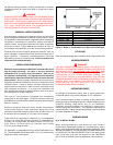
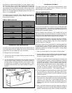
GB MODELS-FLOW, HEAD LOSS AND TEMPERATURE RISE
20 Deg. F Rise 30 Deg. F Rise 40 Deg. F Rise Maximum Flow Rate Minimum Flow Rate
GPM PD-FT GPM PD-FT GPM PD-FT GPM PD-FT Deg. F GPM PD-FT Deg. F
MODEL Head Head Head Head Rise Head Rise
GB - 1000 83 5.1 55 2.7 41.6 1.5 154 12.2 11 42 1.5 40
GB - 1300 109 7.2 72.8 4.2 54.6 3.2 154 14.5 14 55 3.2 40
GB - 1500 126 10.1 84 6.3 63 4.3 154 16.3 17 64 4.3 40
GB - 1850 154 18.5 103.6 10.1 77.7 6.4 154 18.5 20 78 6.4 40
GB - 2100 n/a n/a 117.6 14.5 88 8.3 154 21.3 23 89 8.3 40
GB - 2500 n/a n/a 139.4 18.5 104.6 11.6 154 23.2 28 105 11.6 40
Note: GW models (GB optional) are equipped with pumps capable of handling 50 equivalent feet
(15.2 m) of normal pipe fittings.