


8
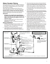
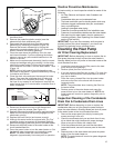
Locate the hot water (outlet) & cold water (inlet) pipes 4.
to the water heater.
Locate the slit running the length of a section of pipe 5.
insulation.
Spread the slit open and slip the insulation over the 6.
cold water (inlet) pipe. Apply gentle pressure along the
length of the insulation to ensure that it is fully seated
around the pipe. Also, ensure that the base of the
insulation is fl ush with the water heater. Once seated,
secure the insulation with duct tape, electrical tape, or
equivalent.
Repeat steps 5 and 6 for the hot water (outlet) pipe.7.
Add additional sections of pipe insulation as needed.8.
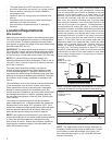
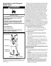
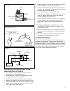
Figure 6
T&P Relief Valve Insulation
T&P Relief Valve
T&P Relief Valve
Drain Line
Manual Relief Lever
T&P Relief Valve Insulation
Electrical Requirements
If you lack the necessary skills required to properly install the
electrical wiring to this water heater, do not proceed but have a
qualifi ed electrician perform the installation.
When making the electrical connections, always make sure:
The electrical service provides 240 VAC to the water heater •
for proper operation. DO NOT use 208 VAC.
Wire sizes and connections comply with all applicable •
codes or in the absence of local or state codes follow
NFPA-70, the National Electrical Code-current edition.
Wiring enclosed in approved conduit (if required by local •
codes).
The water heater and electrical supply are properly •
grounded.
The electrical supply has the proper overload fuse or •
breaker protection.
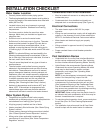
Figures 8A & 9 are provided as reference drawings. Always
reference the wiring diagram located on the water heater for the
correct electrical connections and connect the electrical supply
to the water heater in accordance with local utility requirements
and codes.
When installing the electrical wiring to the water heater:
Although this water heater is equipped with “Dry Fire” 1.
protection circuitry, be sure tank is completely filled with
water, and all air is purged from the tank before making
any electrical connections. See “Draining and Flushing
Section”.
Turn off power to the electrical wiring for the water heater at 2.
the circuit breaker/fuse box.
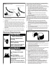
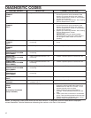
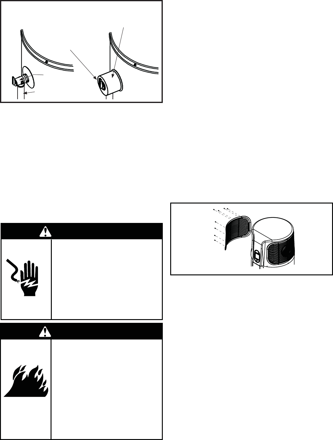
Remove the left louvered access panel (when facing the 3.
water heater) by loosening the screws securing it to the
water heater.
Loosen the screws securing the electrical junction box 4.
cover to the water heater and set aside.
Connect the electrical supply to the water heater. 5.
A standard 1/2 inch opening has been made in the junction
box for conduit connections.
Connect ground wire to green ground wire in the electrical 6.
junction box of the water heater.
Reinstall the junction box cover.7.
Reattach the left louvered access panel to the water heater 8.
and secure it using the screws loosened earlier.
Turn on electrical power to the water heater.9.
Press the power button to turn the water heater on, then 10.
press the Efficiency button to set the operating mode.
NOTE: The water heater will conduct a system diagnostic
(approximately 8 minutes) prior to returning to operation.
Once the diagnostic sequence has finished, the fan should 11.
turn on.
NOTE: The heat pump’s fan will not turn on if the incoming
water temperature is less than 59 °F and/or the ambient
air temperature is above 109 °F or below 45 °F. Should the
internal diagnostics detect a problem with the heat pump,
an error message will be displayed.
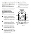
Set the operational mode. For standard installation, the 12.
Hybrid Mode offers the best combination of efficiency
and hot water delivery. For detailed descriptions of all
operational modes see “Adjusting the User Interface
Module/Operational Modes” section.
WARNING
Electric Shock Hazard
Disconnect power before
servicing.
Replace all parts and panels
before operating.
Failure to do so can result in
death or electrical shock.
WARNING
Fire Hazard
Use 10 gauge solid copper
wire.
Use a UL listed or
CSA approved strain relief.
Connect ground wire to green
ground wire.
Failure to do so can result in
death, fire, or electrical shock.
Figure 7
Louvered Panel