


7
To reduce the risk of excessive pressures and temperatures
in this water heater, install temperature and pressure relief
protective equipment required by local codes, but no less
than a combination temperature and pressure relief valve
certifi ed by a nationally recognized testing laboratory that
maintains periodic inspection of the production of listed
equipment or materials, as meeting the requirements for
Relief Valves and Automatic Shutoff Devices for Hot Water
Supply Systems, ANSI Z21.22 - latest edition. This valve
must be marked with the maximum set pressure not to
exceed the marked maximum working pressure of the
water heater. Install the valve into an opening provided
and marked for this purpose in the water heater, and orient
it or provide tubing so that any discharge from the valve
exits only within 6 inches above drain, or at any distance
below, the structural fl oor, and does not contact any live
electrical part. The discharge opening must not be blocked
or reduced in size under any circumstance.
IMPORTANT: Only a new temperature and pressure relief
valve should be used with your water heater. Do not use an
old or existing valve as it may be damaged or not adequate
for the working pressure of the new water heater. Do not
place any valve between the relief valve and the tank.
The Temperature & Pressure Relief Valve:
• Shall not be in contact with any electrical part.
• Shall be connected to an adequate discharge line.
• Shall not be rated higher than the working pressure
shown on the data plate of the water heater.
The Discharge Line:
• Shall not be smaller than the pipe size of the relief
valve or have any reducing coupling installed in the
discharge line.
• Shall not be capped, blocked, plugged or contain
any valve between the relief valve and the end of the
discharge line.
• Shall terminate a maximum of six inches above a floor
drain or external to the building. In cold climates, it is
recommended that the discharge pipe be terminated at
an adequate drain inside the building.
• Shall be of material listed for hot water distribution.
• Shall be installed to allow complete drainage of both
the valve and discharge line.
Temperature/Pressure Relief Valve and
Pipe Insulation
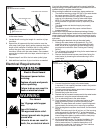
Locate the temperature and pressure relief valve on the 1.
water heater (also known as a T&P relief valve). See
Figure 5.
Locate the slit running the length of the T&P relief valve 2.
insulation.
Spread the slit open and fi t the insulation over the T&P 3.
relief valve. See Figure 6. Apply gentle pressure to the
insulation to ensure that it is fully seated on the T&P Re-
lief Valve. Once seated, secure the insulation with duct
tape, electrical tape, or equivalent.
IMPORTANT: The insulation and tape must not block
the discharge opening or hinder access to the manual
relief lever (Figure 6). Ensure a discharge pipe is in-
stalled into the T&P valve discharge opening per the
instructions in this manual.
Temperature and Pressure
Relief Valve
Explosion Hazard
If the temperature and pressure relief valve
is dripping or leaking, have a qualified
person replace it.
Examples of a qualified person include:
licensed plumbers, authorized electric
company personnel, and authorized service
personnel.
Do not plug valve.
Do not remove valve.
Failure to follow these instructions can
result in death or explosion.
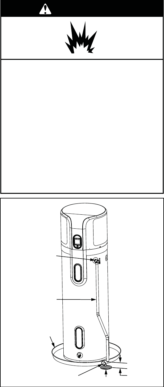
WARNING
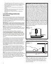
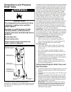
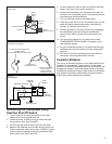
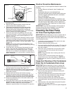
6” Maximum
Air Gap
Drain Pan 2 1/2”
Depth Maximum and
2 Inches wider than
the water heater.
Discharge Pipe
(Do Not Plug or Cap)
Temperature and
Pressure Relief Valve
Drain Line 3/4”
ID Minimum
Drain
Figure 5
Temperature and Pressure
Relief Valve Installation
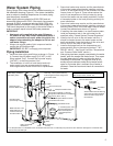
For protection against excessive pressures and
temperatures, a temperature and pressure relief valve must
be installed in the opening marked “T & P RELIEF VALVE”
(See Figure 5).