


10
Water Heater Location
Centrally located with the water piping system. □
The fl ooring beneath the water heater must be able to □
support the weight of the water heater when fi lled with
water (967 lbs. full).
Located indoors (such as a basement or garage) □
and in a vertical position. Sheltered from freezing
temperatures.
Provisions made to shelter the area from water □
damage. Metal drain pan installed and piped to an
adequate drain.
Sufficient room to service the water heater. □
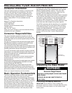
Sufficient air for the heat pump to function. □
The water
heater must be located in a space 750 cubic feet or
larger, and must have unrestricted airfl ow. As an
example, a room that has an 8 foot tall ceiling and is
10 feet long by 9-1/2 feet wide would contain 760 cubic
feet.
NOTE: For optimal effi ciency and serviceability, the
following clearances should be maintained: 3 feet on
the air inlet side, 5 feet on the air outlet side, 6 inches in
the back, and 2 feet in the front.
The unit cannot be placed into any type of closet or □
small enclosure.
The site location must be free from any corrosive □
elements in the atmosphere such as sulfur, fl uorine,
and chlorine. These elements are found in aerosol
sprays, detergents, bleaches, cleaning solvents, air
fresheners, paint, and varnish removers, refrigerants,
and many other commercial and household products.
In addition excessive dust and lint may affect the
operation of the unit and require more frequent
cleaning (See “Cleaning the Heat Pump” section).
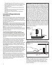
Ambient air temperature must be above 45°F and □
below 109°F. If the ambient air temperature falls
outside these upper and lower limits the electrical
elements will activate to meet the hot water demand.
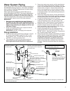
Water System Piping
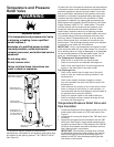
Temperature and pressure relief valve properly □
installed with a discharge pipe run to an adequate drain
and sheltered from freezing (See Figure 5).
All piping properly installed and free of leaks. □
Heater completely filled with water (See “Water Piping □
System” section).
Closed system pressure buildup precautions installed □
(See “Closed System/Thermal Expansion” section).
Mixing valve (when applicable) installed per □
manufacturer’s instructions (See “Water Temperature
Regulation” section).
INSTALLATION CHECKLIST
Condensate Drain Line Installation
Must be located with access to an adequate drain or □
condensate pump.
Condensate drain lines installed and piped to an □
adequate drain or condensate pump (See Figure 4).
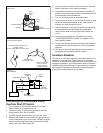
Electrical Connections
The water heater requires 240 VAC for proper □
operation.
Wiring size and connections comply with all applicable □
codes or in the absence of local or state codes follow
NFPA-70, the National Electrical Code-current edition.
Water heater and electrical supply are properly □
grounded.
Wiring enclosed in approved conduit (if required by □
local codes).
Proper overload fuse or circuit breaker protection □
installed.
Post Installation Review
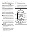
Understand how to use the User Interface Module to □
set the various modes and functions (See “Adjusting
the User Interface Module/Operating Modes” section).
Hybrid Mode is the recommended Operating Mode. □
Understand the various Operating Modes and which
mode may be best based on season, ambient
temperature, and usage (See “Operating Mode
Description” section).
NOTE: It may be necessary to temporarily change
modes if for example filling a spa or hot tub.
Understand the importance of routine inspection/ □
maintenance of the condensate drain pan and lines
(See “
Inspection/Cleaning of the Condensate Drain
Pan & Condensate Drain Lines” section). This is to
help prevent any possible drain line blockage resulting
in the condensate drain pan overflowing.
IMPORTANT: Water coming from the plastic shroud is
an indicator that both condensation drain lines may be
blocked. Immediate action is required.
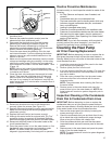
To maintain optimal operation check, remove and clean □
the air filter (See “Air Filter Cleaning/Replacement”
section).
The Installation Instructions and Use & Care Guide □
should be kept with the water heater for reference.