


5
Water System Piping
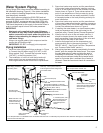
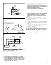
Piping, fi ttings, and valves should be installed according to
the installation drawing (Figure 4). If the indoor installation
area is subject to freezing temperatures, the water piping
must be properly insulated.
Water supply pressure should be 50-60 PSIG and not
exceed the maximum 80 PSIG. If the supply line pressure
exceeds 80 PSIG, a pressure reducing valve (PRV) with
a bypass should be installed in the cold water supply line.
This should be placed on the supply to the entire house in
order to maintain equal hot and cold water pressures.
IMPORTANT:
•
Heat must not be applied to the water fittings on
the heater as they may contain nonmetallic parts. If
solder connections are used, solder the pipe to the
adapter before attaching the adapter to the hot and
cold water fittings.
• Always use a good grade of joint compound and be
certain that all fittings are tight.
IMPORTANT: DO NOT over apply joint compound.
Piping Installation
Install the water piping and fittings as shown in Figure 1.
4. Connect the cold water supply (3/4” NPT) to the
fitting marked “Cold”. Connect the hot water supply
(3/4” NPT) to the fitting marked “Hot”.
The installation of unions in both the hot and cold 2.
water supply lines are recommended for ease of
removing the water heater for service or replacement.
Some local codes may require, and the manufacturer 3.
of this water heater recommends, installing a mixing
valve or an anti-scald device in the domestic hot water
line as shown in Figure 4. These valves reduce the
point-of-use temperature of the hot water by mixing
cold and hot water and are readily available. Contact
a licensed plumber or the local plumbing authority for
more information.
Some local codes may require, and the manufacturer 4.
of this water heater recommends, installing a pressure
reducing valve (PRV) in the cold water inlet line where
it enters the residence as shown in Figure 4.
If installing the water heater in a closed water system, 5.
install an expansion tank in the cold water line as
specified under “Closed System/Thermal Expansion.”
Install a shut off valve in the cold water inlet line. It 6.
should be located close to the water heater and be
easily accessible. Know the location of this valve and
how to shut off the water to the heater.
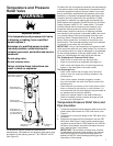
Install a discharge line from the temperature and 7.
pressure relief valve in the opening marked “T & P
RELIEF VALVE”. See Figure 5 and the “Temperature
and Pressure Relief Valve” section.)
After piping has been properly connected to the water 8.
heater, open the nearest hot water faucet. Then open
the cold water shut off valve and allow the tank to
completely fill with water. To purge the lines of any
excess air and sediment, keep the hot water faucet
open for 3 minutes after a constant flow of water is
obtained. Close the faucet and check all connections
for leaks.
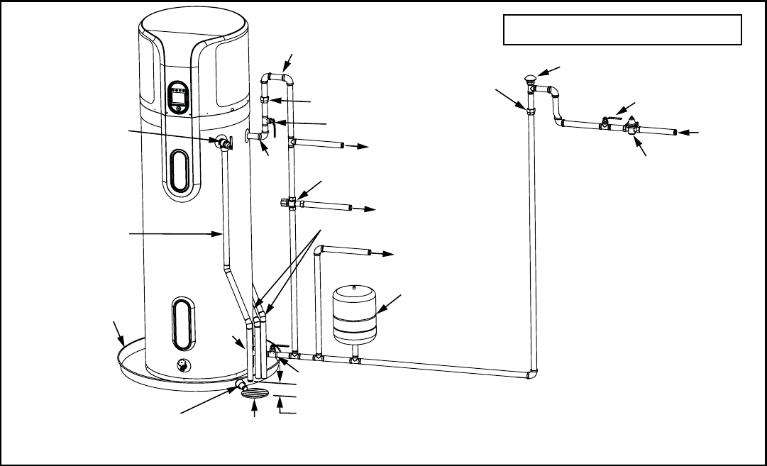
Cold Water
Inlet Valve
Cold Water
Inlet
Whole House Pressure Reducing
Valve (PRV) should be installed
where the water supply enters
the residence.
In a closed system, use a
thermal expansion tank.
See “Closed System/
Thermal Expansion”
section.
Cold Water Outlet
Shut-off Valve
(Cold)
Tempered Water to Fixtures
Untempered Water Outlet
Vacuum Relief Valve
Mixing Valve (Optional) - Follow the
Mixing Valve’s Manufacturer’s Installation
Instructions. (Set to 120° F)
6” Maximum
Air Gap
Metal Drain Pan 2 1/2”
Depth Maximum and
2 Inches wider than
the water heater.
Discharge Pipe
(Do Not Cap or Plug)
Temperature and
Pressure Relief Valve
Union
Shut-off Valve (Hot)
Drain Line 3/4”
ID Minimum
Drain
Condensate Drain Lines*
Massachusetts: Install a vacuum relief in cold
water line per section 19 MGL 142.
Figure 4
Water Piping Installation
with Mixing Valve
* If an adequate drain is not available for the condensate drain lines then a condensate pump should be used. DO NOT discharge the condensate drain
lines into the metal drain pan.
Union
Hot
(Outlet)
Cold
(Inlet)
Heat Trap - The top of the heat trap
must be higher than the storage tank
of the water heater.