


6
Please note the following:
• The system should be installed only with piping that is
suitable for potable (drinkable) water such as copper,
CPVC, or polybutylene. This water heater must not be
installed using iron piping or PVC water piping.
• Use only pumps, valves, or fittings that are compatible
with potable water.
• Use only full flow ball or gate valves. The use of valves
that may cause excessive restriction to water flow is
not recommended.
• Use only 95/5 tin-antimony or other equivalent solder.
Any lead based solder must not be used.
• Piping that has been treated with chromates, boiler
seal, or other chemicals must not be used.
• Chemicals that may contaminate the potable water
supply must not be added to the piping system.
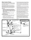
Condensate Drain Line Installation
Install two 1/2” PVC discharge lines from the condensate
drains (located on the right side near the back). The lines
should terminate a maximum of six inches above an
adequate drain. Do not discharge the condensate drain
lines into the metal drain pan. If no floor drain is available
or the drain is above the level of the condensate line, a
condensate pump should be installed. These pumps are
available from local distributors.
When installing the drain line, note the following:
Plastic pipe or tubing must be used to connect the •
condensate drain to a suitable drain or condensate
pump.
Condensate drain lines should be installed in •
conditioned areas only. Install approved insulation on
the condensate drain lines to prevent condensation
from forming on the outside of the drain lines.
Condensation drain lines installed in areas that are
subject to freezing temperatures should be wrapped
with a nationally recognized/listed heat tape. Install per
manufacturer’s instructions.
Do not connect condensate drain lines with other drain •
or discharge lines into a single (common) pipe or line.
Each line (condensate drain line, temperature and
pressure relief valve discharge pipe, etc) should be
independently run to an adequate drain.
Slope the condensate drain lines toward the inside •
floor drain or condensate pump.
The condensate drain lines and connections to the •
drain piping must comply with all local codes.
Use appropriate primer and glue to cement the •
condensate drain lines to the heat pump drain pan.
NOTE: The heat pump drain pan is ABS and the two
condensate drain pipes should be PVC.
If a condensate pump is installed it should shut off •
the heat pump in the event the condensate pump
fails or the float switch in the pump activates (See
“Condensate Pump Installation” section.)
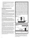
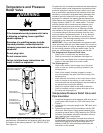
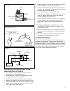
Closed System/Thermal Expansion
Explosion Hazard
If the temperature and pressure relief valve
is dripping or leaking, have a qualified
person replace it.
Examples of a qualified person include:
licensed plumbers, authorized electric
company personnel, and authorized service
personnel.
Do not plug valve.
Do not remove valve.
Failure to follow these instructions can
result in death or explosion.
WARNING
Most public water systems in North America are required
to prevent water flowing from points of use (residences,
businesses, etc.) back into the supply system in order
to maintain water quality. To accomplish this, back flow
preventers such as check valves, are installed in the water
line going to each point of use. Typically the back flow
preventer will be installed at the water meter or inside a
building where the supply line enters the building. This
device allows water to flow into the residence but does
not allow it to flow back into the water supply. This creates
what is known as a “Closed System”. As water is heated
by the water heater, the water in the system attempts to
expand, but has nowhere to go resulting in an increase
in pressure. This increase in pressure in the system may
cause the temperature-pressure relief valve to open to
relieve the pressure. Water will drip from the temperature
and pressure relief valve. Premature tank failure will result
if this condition is not corrected. To prevent this condition, a
properly-sized thermal expansion tank should be installed
in the cold water supply to the water heater as shown in
Figure 4. Failure to install a properly sized expansion tank
in a closed system will void the warranty on the water
heater in the event of tank failure. It is important to follow
the thermal expansion tank manufacturers’ installation
instructions and to adjust the expansion tank pressure
to match the water supply pressure. Contact a plumbing
service agency or your retail supplier regarding the
installation of a thermal expansion tank.