


9
Important: Air for combustion and ventilation must not
come from a corrosive atmosphere. Any failure due to
corrosive elements in the atmosphere is excluded from
warranty coverage.
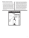
Vent Pipe System
This is a direct vent water heater which draws its combustion
air from outside of the structure and exhausts all products
of combustion to the outside of the structure.
Through-the-wall installations require locating the water
heater next to an outside wall. All necessary components
are supplied for the standard through-the-wall installation.
Optional vertical and horizontal extension kits are available
for installations that exceed the standard horizontal and
vertical distances (see table at right). Only one vertical and
one horizontal kit can be used on the same installation.
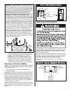
Through the Wall Venting
1. Make sure a proper location has been selected for the
water heater installation. Consider the following:
· Water piping
· Gas Piping
· Access for service
· Proper clearance for combustibles
· Drainage for the temperature and pressure relief
valve and drain pan.
· Vent cap termination
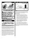
2. Determine the A dimension for your specific water heater
by referencing figure 7. Cut a 6 inch opening through the
wall in the location as shown. Determine the location of
electrical wiring, pipes, or wall studs before cutting.
NOTE: Installations requiring an A dimension (vertical
height) greater than what is shown as standard in the table
will require the use of a vertical extension kit (See Vertical
Install Kit on Page 10).
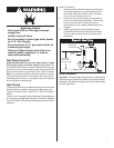
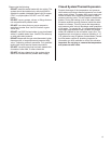
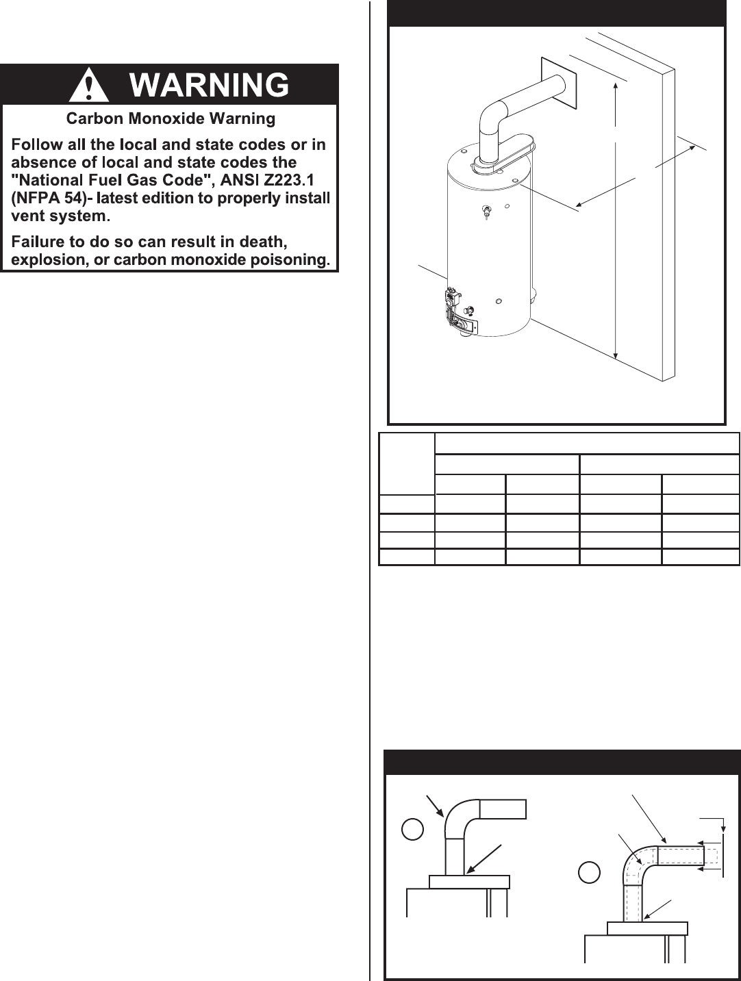
3. If you are not using the vertical extension kit, place the
3 elbow on the flue pipe reducer on the air box and point
it in the desired direction (See Figure 8). Press it firmly
downward until seated. Drill 4 holes 90
° apart with a 1/8
drill bit and fasten the four #8 sheet metal screws provided.
Apply silicone sealant to the joint. Install the 5 elbow
over the 3 elbow and seat it into the collar on the air box.
Drill 4 holes 90° apart with a 1/8 drill bit and fasten the
four #8 sheet metal screws provided. Apply silicone
sealant to the joint. Place the inner wall cover plate over
the 5 elbow. This plate will be positioned later.
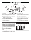
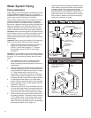
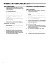
Figure 7: A & B Dimensions
Figure 7: A & B Dimensions
KIT
CAPACITY
40 GALLON
50 GALLON
A
B
A
B
62.75
62.75
62.75 - 89.75
62.75 - 89.75
15.75 - 24.50
27.00 - 38.00
15.75 - 24.50
27.00 - 38.00
STANDARD
HORIZONTAL
VERTICAL
BOTH
71.00
71.00
71.00 - 98.00
71.00 - 98.00
15.75 - 24.50
27.00 - 38.00
15.75 - 24.50
27.00 - 38.00
Figure 8: Vertical Installation
3 Elbow
Screws &
Sealant
1
2
5 Pipe
3 Elbow
Inside Cover
Plate
Screws
& Sealant
B
A
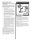
Combustion Air Supply and
Ventilation
NOTE:
1. Dim. A measured from center of cutout to bottom of heater.
2. Dim. B measured from center of heater to outside of wall.