


5. Replace the (6) screws which secure the manifold
assembly door to the combustion chamber. Tighten
securely. There should be no space between the
gasket part of the manifold door and combustion
chamber. Do not operate the water heater if the
door gasket is not sealed.
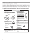
6. Reconnect the manifold tubing (L.P. models have left-
hand threads), pilot tubing, and thermocouple to
the thermostat. Do not cross-thread or apply any thread
sealant to these fittings. The thermocouple nut should
be started and turned all the way in by hand. An
additional quarter turn with a 3/8 open-end wrench
will then be sufficient to seat the lockwasher.
7. Reconnect the igniter wire.
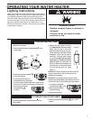
8. Turn gas supply on and refer to the "Lighting
Instructions" on page 17-18.
24
Testing the Igniter System
Turn off the gas to the water heater at the manual gas
shut-off valve. Watch the electrode tip while activating
the igniter. A visible spark should jump from the electrode.
To avoid shock, do not touch the burner or any metal
part on the pilot or pilot assembly. If no spark is visible,
check the wire connections and make sure the electrode
is not broken. Replace the igniter if defective.
Dirt and rust on the pilot or electrode tip can prevent
the igniter spark. Wipe them with a damp cloth and dry
completely. Rust can be removed from the electrode
tip and metal surfaces by lightly sanding with an emery
cloth or fine grit sandpaper.
Removing and Replacing the Gas
Control Valve/Thermostat
Important: The gas control valve/thermostat is a standard
valve. Use only factory authorized replacement parts.
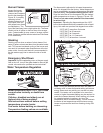
1. On the gas control valve/thermostat turn the
temperature dial counterclockwise to its lowest
setting. Turn the gas control knob clockwise to
the "OFF" position (Figure 17).
2. Turn off the gas at the manual shutoff valve on
the gas supply pipe (Figure 6).
3. Drain the water heater. Refer to the section of
"Draining and Flushing" on page 21 and follow
the procedure.
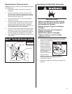
4. Disconnect the igniter wire from the igniter button.
Remove the igniter button by depressing front and
rear holding tabs and lift. Disconnect the
thermocouple, pilot tube, and manifold tube (L.P.
models have left-hand threads) at the thermostat
(Figure 19).
5. Refer to "Gas Piping" (Figure 6) and disconnect
the ground joint union in the gas piping. Disconnect
the remaining pipe from the gas valve/thermostat.
Notice: When removing the gas control valve/thermostat
do not use pipe wrench or vise to grip body. Do not
insert any type of blunt instrument into the inlet or outlet
connections. Using these type tools may result in damage
to the gas control valve/thermostat.
6. Turn the gas control valve/thermostat
counterclockwise. Remove the gas control
valve/thermostat.
To replace the gas control valve/thermostat reassemble
in reverse order.
· Be sure to use approved Teflon tape or pipe joint
compound on the gas piping connections and
fitting on the back of gas valve that screws into
tank.
· Be sure to remove the pilot ferrule nut from the
new gas control valve/ thermostat.
· Turn gas supply on and check for leaks. Use a
chloride-free soap and water solution (bubbles
forming indicate a leak) or other approved method.
· Be sure tank is completely filled with water before
lighting and activating the water heater. Follow
the "Lighting Instructions" on page 17-18.
· If additional information is required, contact the
Service Department at: 1-800-999-9515.
9. Check for leaks. Use a chloride-free soap and water
solution (bubbles forming indicate a leak) or other
approved method. All leaks must be fixed
immediately.
10. Replace the outer door.
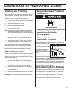
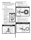
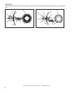
Piezoelectric Igniter System
The piezoelectric igniter system consists of the igniter button,
electrode and wire. The pilot is ignited by an electric spark
generated when the igniter button is pressed. The spark gap
of 0.125 inch is set when the electrode is installed at the
factory. (See Figure 24A and 24B). Use only factory
authorized piezoelectric igniter parts for replacement.
Igniter
Button
Pilot
Thermocouple
Electrode
Wire
to
electrode
Tip
.125
Snap-on Connector
Figure 24B: L.P. Ignitor Assembly
Figure 24A: Natural Gas Ignitor Assembly
Igniter Button
Wire
to
Electrode
Snap-on Connector
Electrode
Tip
Pilot
Thermocouple
.125