


10
9. Position and fasten the inner wall plate to the inside wall
using an appropriate fastener for the specific wall
construction. Apply silicone sealant between the inner
wall plate and the inside wall.
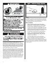
10. Make certain the 5 telescoping pipe has been fully
engaged onto the 5 inch elbow. Drill two 1/8 holes 180°
apart at the junction of the two joints. Secure with four
#8 sheet metal screws and apply silicone sealant to the
seams. Make sure all the 5 pipe joints are sealed including
the joint to the collar on the water heaters air supply box
(See Figure 9).
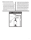
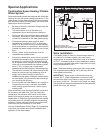
4. Extend the 3 telescoping pipe to its maximum length.
Place the smaller section onto the 3 elbow at least 1 and
1/2 inches (See Figure 9). Drill two holes 180° apart
and secure with the two #8 sheet metal screws provided.
Apply silicone sealant to the joint.
5. Attach the larger section of the 5 telescoping pipe to the
flange on the outer wall plate (See Figure 9). Drill holes
90° apart with a 1/8 drill bit and fasten with four #8 sheet
metal screws (provided). Apply silicone sealant to the
seam.
6. Extend the 5 telescoping tube to its maximum length.
From outside of the building, insert a 5 tube/outer wall
plate assembly through the opening in the exterior wall
and onto the 5 elbow (See Figure 9). Seat the base of
the outer wall plate onto the exterior wall. Apply silicone
sealant between the plate and the exterior wall.
Figure 9: Vertical Installation
3 Pipe
Inner Wall
Plate
Screws
& Sealant
3 Telescoping
Pipe
Wall
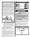
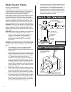
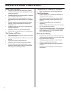
7. Place the 3 tube located in the vent cap into the end of
the 3 telescoping tube (See Figure 10). Drill two holes
180° apart with a 1/8 drill bit and secure with two #8
sheet metal screws. Apply sealant to the joint. Seat the
cap against outer wall plate with the word HOT in an
upright position.
8. Secure the vent cap/outer wall plate assembly to the
exterior wall with the four 1 and 1/2 screws provided
(See Figure 10). Varying wall structures may require a
different type of screw anchor. To prevent rain from
entering the water heater vent pipe, the 5 tube should
be sloped downward towards the wall 1/4 per foot.
Figure 10: Vertical Installation
5 Elbow
Inner Wall
Plate
Screws
& Sealant
3 Telescoping
Pipe
5 Telescoping Pipe
Outer Wall Plate
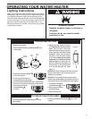
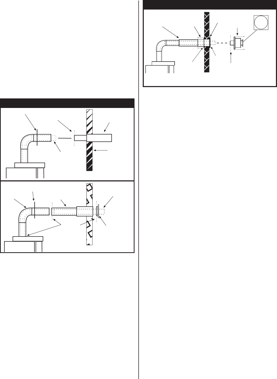
Inner Wall
Plate
Screws
& Sealant
Outer
Wall
Plate
HOT
Screws
Vent Cap
Screws
Sealant
Slope down 1/4
per foot
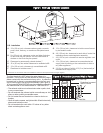
Optional Vertical Extension Kit
Installations requiring dimension "A" to be greater than 62.75
(40 Gallon) or 71.00 (50 Gallon) will require the use of the
optional vertical extension kit. The maximum height of the
"A" dimension cannot exceed 98 inches. If the "A" dimension
for your application is less than 98 inches, you will have to
cut the 3 and 5 inch pipes in the vertical extension kit to the
correct length. For example, if your applicable "A" distance
is 80 inches, then 98 inches - 80 inches = 18 inches. Therefore,
you will need to cut 18 inches from both the 3 and 5 inch
vertical extension pipes. DO NOT CUT THE CRIMPED END
OF THE 5 INCH PIPE.
After cutting both the pipes to the proper size, place the 3
vertical extension pipe over the flue pipe reducer on the
upper air box and press it firmly downward until seated. Using
a level, make sure the extension tube is pointing straight up.
Drill 4 holes 90° apart with a 1/8 drill bit and fasten with four
#8 sheet metal screws (provided). Apply silicone sealant to
the seam.
Place the uncrimped end of the 5 inch extension pipe over
the 3 inch extension pipe and seat it onto the collar on the
air box. Making sure the 3 inch extension pipe is centered
in the 5 inch pipe, drill four holes 90° apart with the 1/8 drill
bit and fasten with four #8 sheet metal screws (provided).
Apply silicone sealant to the seam. Place the flared end of
the 3 inch elbow over the 3 inch extension pipe and press
it firmly downward until seated. Drill four holes 90° apart with
the 1/8 drill and fasten with four #8 sheet metal screws
(provided). Apply silicone sealant to the seam.
Install the 5 inch elbow over the 3 inch elbow and seat it
down onto the crimped end of the 5 inch extension pipe.
Temporarily place the 5 inch telescoping pipe onto the 5 inch
elbow and adjust it to give a 1/4 inch per foot downward
slope to the outside wall. Secure the 5 inch elbow to the
extension pipe by drilling four holes 90° apart with the 1/8
drill and inserting four #8 sheet metal screws. Apply silicone
sealant to the joint. Place the inner wall cover plate over the
5 inch elbow. This plate will be positioned later. Proceed to
step 4.