


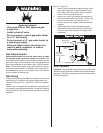

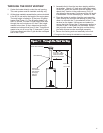
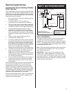

For protection against excessive pressures and
temperatures, a temperature and pressure relief valve
must be installed in the opening marked T & P RELIEF
VALVE (see Figure 14). This valve must be design
certified by a nationally recognized testing laboratory
that maintains periodic inspection of the production of
listed equipment or materials as meeting the
requirements for Relief Valves and Automatic Shut-off
Devices for Hot Water Supply Systems, ANSI Z21.22.
The function of the temperature and pressure relief
valve is to discharge water in large quantities in the
event of excessive temperature or pressure developing
in the water heater. The valve's relief pressure must
not exceed the working pressure of the water heater
as stated on the data plate.
Explosion Hazard
If the temperature and pressure relief valve
is dripping or leaking, have a licensed
plumber correct the problem.
Do not plug valve.
Do not remove valve.
Failure to follow these instructions can
result in death, or explosion.
Important: Only a new temperature and pressure relief
valve should be used with your water heater. Do not
use an old or existing valve as it may be damaged or
not adequate for the working pressure of the new water
heater. Do not place any valve between the relief valve
and the tank.
The Temperature & Pressure Relief Valve:
· Must not be in contact with any electrical part.
· Must be connected to an adequate discharge line.
· Must not be rated higher than the working pressure
shown on the data plate of the water heater.
The Discharge Line:
· Must not be smaller than the pipe size of the relief
valve or have any reducing coupling installed in
the discharge line.
· Must not be capped, blocked, plugged or contain
any valve between the relief valve and the end of
the discharge line.
· Must terminate a maximum of 6 inches above a
floor drain or external to the building.
· Must be capable of withstanding 250°F (121°C)
without distortion.
· Must be installed to allow complete drainage of
both the valve and discharge line.
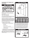
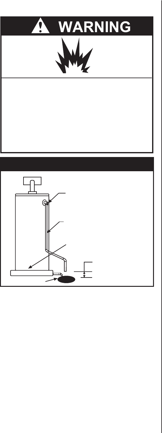
Temperature and Pressure
Relief Valve
Discharge Line
3/4 Inch Min.
DO NOT CAP OR PLUG
6 inch maximum
Drain pan
Drain
Figure 14: T & P Valve Installation
14
Temperature and Pressure
Relief Valve