


ENGLISH
USER MANUAL
4 FLOORTEC 560 B 146 2590 000(1)2005-03 A
– In case of part replacement, order ORIGINAL spare
parts from an authorised Dealer or Retailer.
– To ensure the proper and safe operation of the
machine, have the scheduled maintenance, detailed
in the related chapter of this Manual, performed by
the authorised personnel or an authorised Service
Center.
– The machine must be disposed of properly, because
of the presence of toxic-harmful materials (batteries,
oils, etc.), which are subject to standards that require
disposal in special centres (see the Scrapping
chapter).
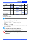
– If the machine is used according to the instructions,
the vibrations do not cause dangerous situations. The
machine vibration level is less than 2.5 m/s
2
.
– When lead batteries (WET) are installed on this
machine, do not tilt the machine more than 30° from
its horizontal position to not allow the highly corrosive
acid to leak out of the batteries. When the machine is
to be tilted for maintenance operations, remove the
batteries.
UNPACKING
Upon delivery carefully check that the machine and its
packing, if any, have not been damaged during
transportation. In case of visible damages, keep the
packing and have it checked by the Parcel Service that
delivered it. Call the Carrier immediately to fill in a damage
claim.
Please check that the following items have been supplied
with the machine:
1. Technical documents: Sweeper Use and
Maintenance Manual, Electronic Battery Charger
Manual (if installed on the machine), Spare Part List
2. No. 1 main fuse
3. No. 1 side broom fuse
MACHINE DESCRIPTION
OPERATION CAPABILITIES
The sweeper is used to sweep dust or light debris on
smooth and solid floor, in civil or industrial environment,
under safe operation conditions by a qualified Operator.
Control panel
(See Fig. B)
1. Control panel
2. Ignition switch
3. Discharged battery warning light
4. Semi-discharged battery warning light
5. Charged battery warning light
6. Display
7. Display selection push-button:
– Hour meter
– Hour and minutes meter
– Battery voltage (V)
8. Filter-shaker switch (optional)
9. Panel fastening screws
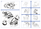
Exterior general overview
(See Fig. C)
1. Front skirt lifting lever
2. Side broom retainer
3. Handlebar
4. Selector lever
5. Handlebar inclination adjusting knobs
6. Can holder
7. Hood
8. Rear wheels on fixed axle
9. Front steering wheel
10. Side broom
11. Main broom
12. Side broom lifting and adjusting knob
13. Left side skirt
14. Right side skirt
15. Front skirt
16. Rear skirt
17. Hopper
18. Hopper hook
19. Hopper handle
20. Manual filter-shaker handle
21. Main broom movable door
22. Main broom height left adjuster
23. Main broom height right adjuster
24. Main broom right door
25. Main broom right door fixing screws
26. Pedal brake on front wheel (optional)
NOTE
Forward, backward, front, rear, left or right are
intended with reference to the operator’s
position, that is to say on the driver’s seat with
the hands on the handlebar (3, Fig. C).