


USER MANUAL
ENGLISH
146 2590 000(1)2005-03 A FLOORTEC 560 B 11
DUST FILTER CLEANING AND INTEGRITY
CHECK
1. Drive the machine on a level ground and activate the
pedal brake (26, Fig. C) (if present).
2. Turn the ignition key (2, Fig. B) to “0” position.
3. Disengage the retainer (18, Fig. C).
4. Remove the hopper (17) by using the handle (19, Fig.
C).
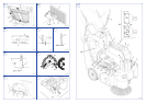
5. Turn the handle (1, Fig. L) upwards (90°
approximately) and let the filter frame (2) rotate
outwards.
6. Pull out the dust filter (3) upwards.
7. In an appropriate outdoor area, clean the filter
shaking it on a level and clean surface, tapping the
side (1, Fig. M) opposite the wire gauze (2). Complete
the cleaning by using compressed air (3) at max. 6
bars, blowing only from the side protected by the wire
gauze (2).
According to the filter type, observe the following
cautions:
– Paper filter (standard): do not use water or
detergents to clean it; the filter can be damaged.
– Polyester filter (optional), to clean it, see the
above-mentioned instructions. For a better
cleaning, it is allowed to wash the filter with water
and non-lathering detergents. This provides better
quality cleaning but reduces the life of the filter,
which will have to be replaced more frequently.
The use of unsuitable detergents can damage the
filter.
8. Check the filter body for tears.
9. If necessary, clean the filter compartment rubber seal
(4, Fig. L) along its perimeter and check it for integrity.
If necessary, replace it.
10. Install in the reverse order of removal (steps from 8 to
1).
SKIRT HEIGHT AND OPERATION CHECK
1. Drive the machine on a level ground that is suitable
for checking the skirt height. Activate the pedal brake
(26, Fig. C) (if equipped) or lock the wheels.
2. Turn the ignition key (2, Fig. B) to “0” position.
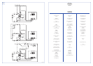
Side skirt check
3. Check the side skirts (13 and 14, Fig. C) for integrity.
Replace the skirts when they have cuts (1, Fig. N)
larger than 20 mm or cracks (2) larger than 10 mm
(for skirt replacement, refer to the Service Manual).
4. Check that the side skirt (13 and 14, Fig. C) height
from the ground is within 0 – 3 mm (Fig. O). If
necessary, adjust the skirt height, proceeding as
follows.
Left side skirt
a) Open the hood (7, Fig. C), loosen the knob (3, Fig. E)
and remove the broom left cover (1, Fig. F), pushing
downward to disengage the retainers (2).
b) Adjust the skirt (3, Fig. F) height using its slots (4).
c) Reassemble the removed components in the reverse
order of disassembly.
Right side skirt
a) Remove the main broom, as described in the related
paragraph.
b) Remove the belt (12, Fig. U) from the pulley (14); to
facilitate the operation, make the pulley (14) rotate
operating on the fan (16).
c) Remove the screws (25, Fig. C) and the right cover
(24) together with the belt (12, Fig. U).
d) On the machine, adjust the skirt (1, Fig. S) height by
using its slots (2).
e) Reassemble the removed components in the reverse
order of disassembly.
Front and rear skirt check
5. Remove the main broom, as described in the related
paragraph.
6. Check the front (1, Fig. R) and rear (2) skirts for
integrity.
7. Replace the skirts when they have cuts (1, Fig. N)
larger than 20 mm or cracks (2) larger than 10 mm
(for skirt replacement, refer to the Service Manual).
8. Check that:
– the front skirt (1, Fig. P) lightly touches the ground
and that, however, it is not detached from ground
(as shown in figure).
– the rear skirt (1, Fig. O) height from ground is
within 0 - 3 mm (as shown in figure).
NOTE
Besides the standard paper filter, polyester
filters are also available. The following
procedure is applicable to each type of filter.
NOTE
Reinstall the filter with the wire gauze (2, Fig.
M) facing the front part of the machine (facing
the fan (16, Fig. U)).