


American-Lincoln 1-27
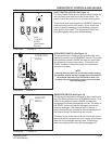
ATS 46/53 Battery
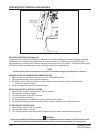
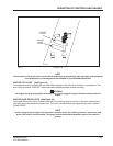
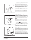
HOPPER DOOR LEVER (See Figure 27)
The hopper door lever is located on the operator’s com-
partment and is used to close and open the hopper dump
door. The lever is a two position hydraulic valve that is
spring loaded to the center position which “HOLDS” the
hopper door in position.
To open the hopper dump door for sweeping or dumping,
push the lever to the “OPEN” direction.
To close the hopper dump door for dumping or transport-
ing, push the lever fully back in the “CLOSE” direction,
and hold for 3 seconds or until you hear the door close.
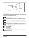
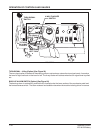
HOPPER LIFT LEVER (See Figure 28)
The hopper lift lever is located on the operator’s compart-
ment console. The lever is a two position hydraulic valve
that controls the operation of the hopper lift system. The
lever is spring loaded to the center position which stops
hopper movement and “HOLDS” the hopper at the present
position.
To raise the hopper for dumping, move the lever to the
“RAISE” position and hold until the hopper reaches the
desired height, then release.
WARNING
The hopper may drop unexpectedly and cause injury,
always engage the safety arm before working under the
hopper.
To lower the hopper after dumping, move the lever to the
“LOWER” position until the hopper is fully lowered and
seated in the machine, then release.
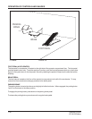
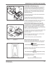
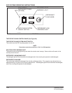
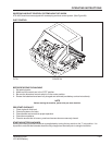
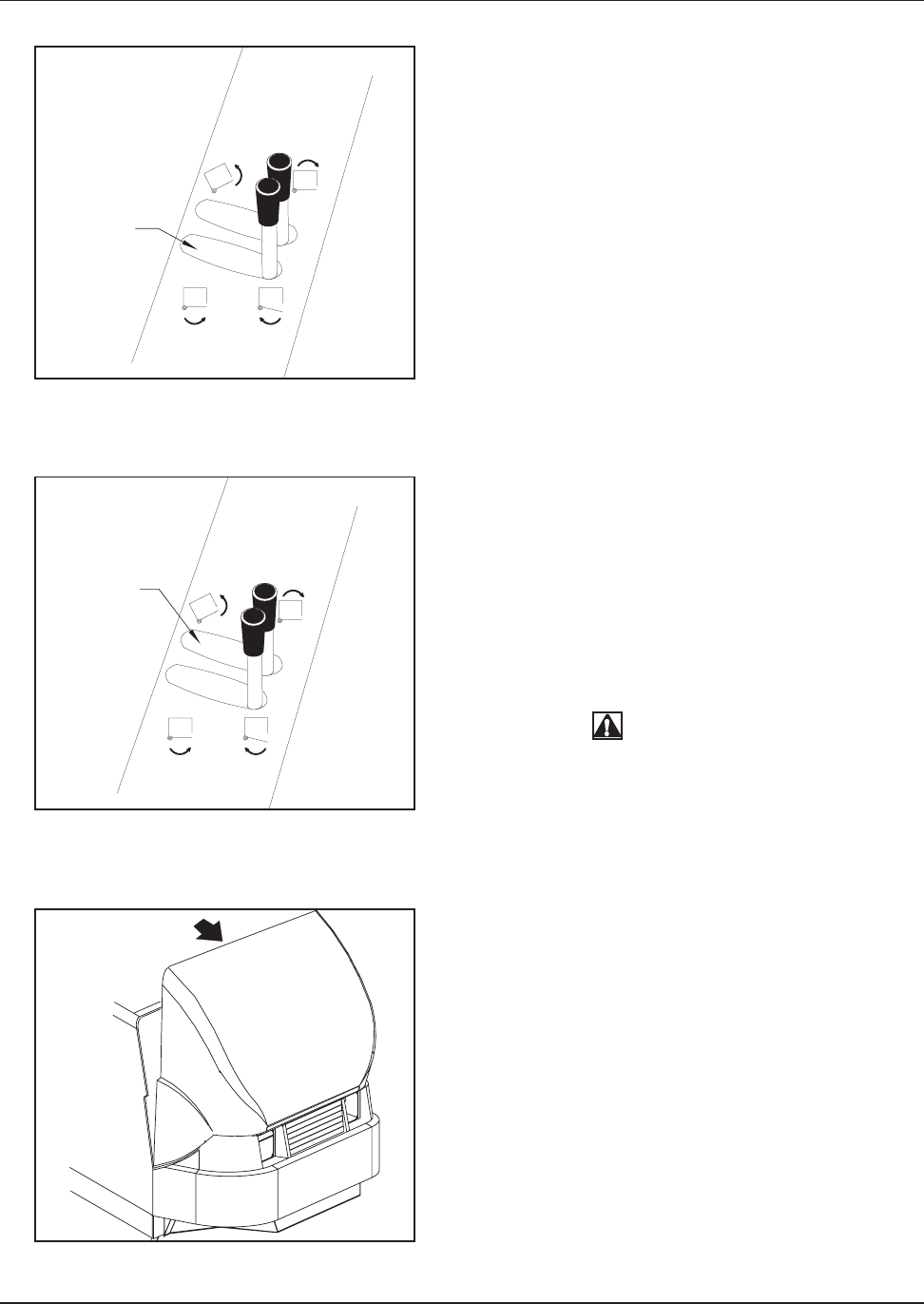
HOPPER FILTER COVER
(See Figure 29)
The hopper filter cover is actually the front cover or “hood”
of the machine. It opens forward by releasing latches to
access the filter compartment for service/inspection of the
dust control filter and optional hopper temp sensor.
Inspect gaskets daily. Replace any gaskets that show
signs of deterioration. Failure to maintain the gaskets in
serviceable condition will degrade dust control at the floor
and will result in less than optimal sweeping performance.
LIFT TOOPEN
HOPPER
LEVER
HOPPER
DOOR
LEVER
(VariableDump
Hopper Only)
C1717A FIGURE 27
C1725A-batt FIGURE 29
C1717B FIGURE 28
OPERATION OF CONTROLS AND GAUGES