


1-16 American-Lincoln
ATS 46-53 Battery
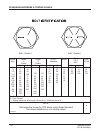
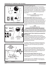
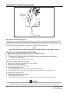
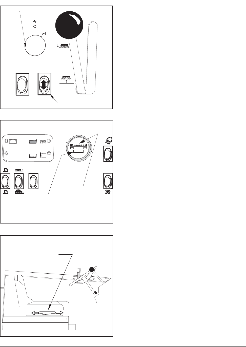
KEY SWITCH (See Figure 3)
The keyed ignition switch is located on the instrument
panel to the left of the side broom lever. The key switch is
a two-position switch that controls power to the machine
systems and accessories. The “OFF” position (O position)
will shut off the machine. The IGN/ON position (I position)
provides power to the machine and all its systems and
accessories.
NOTE
The operator should never leave the machine
unattended while it is on.
FORWARD/REVERSE SWITCH (See Figure 3)
A two-position switch controls the machine’s direction and
is located on the righthand side of the instrument panel
directly below the key switch. Pushing the upper portion of
the switch will provide forward motion when the foot pedal
is pressed. Pushing the bottom portion of the switch will
make the machine move in reverse when the foot pedal is
pressed.
NOTE
The machine will not move if:
The operator is not seated properly in the operator’s
compartment due to the Seat Switch Interlock safety
feature; or if the foot pedal is depressed or depressed too
quickly after turning the key switch on as a result of the High
Pedal Disable safety feature. (See “MillipaK SEM Controller”)
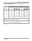
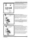
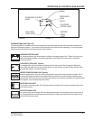
COMBINATION BATTERY CONDITION & HOUR METER
(See Figure 4)
The combination battery condition and hour meter is
located on the instrument panel next to the warning bank.
The meter is activated when the key switch is placed in the
ignition position. The hour meter indicates the actual “run”
time of the machine and can be used to determine ma-
chine maintenance intervals.
The battery condition meter indicates the charge level of
the batteries. The batteries are sufficiently charged if all
the amber LEDs are illuminated during the machine’s
operation.
If the LED on the far left displays red while using the
machine, the low voltage lockout safety feature will shut
down the scrub deck’s operation. The batteries must now
be fully charged in order to reset the low voltage lockout
and continue the cleaning operation.
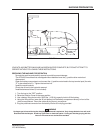
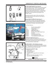
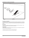
SEAT POSITION ADJUSTMENT (See Figure 5)
The seat position adjustment lever is located on the right
side of the seat base. The lever is spring loaded to the
“LOCK” position.
To adjust the seat, push “FORWARD” on the lever and
move the seat to the desired position. Then release the
lever to “LOCK” the seat into place.
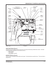
OPERATION OF CONTROLS AND GAUGES
SEAT
POSITION
ADJUSTMENT
LEVER
TO ADJUST
TO
LOCK
C-0508a
HOUR
METER
BATTERY
CONDITION
METER
KEY
SWITCH
FWD/REV
SWITCH
C1631A-batt FIGURE 3
C1633-batt FIGURE 4
C0508A-2 FIGURE 5