STEP 4:
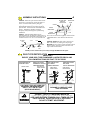
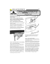
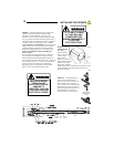
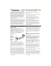
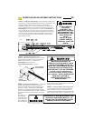
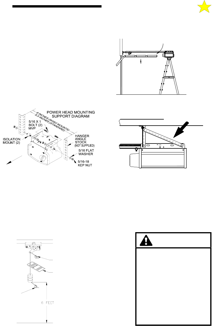
Mount Power Head to Ceiling: Since there is such variety in ceiling structures, all the mounting
possibilities for the Power Unit cannot be illustrated here. The main concern is mounting the Power Unit securely
to the ceiling joists for operational strength, rigidity and safety. Although there are a series of mounting slots
provided on the power unit, try to secure the mounting
straps in the slots closest to the front. Mounting may
usually be accomplished using standard
1-1/4“ perforated steel angle available at most hardware
stores. If in doubt about location of, and attachment to,
ceiling joists, a carpenter should be contacted to provide
assistance. A cross brace will be necessary if power head
is mounted 8” or more from the ceiling.
STEP 5:
Return to the Tee Rail/Front Mounting
Bracket and securely tighten the bolt and nut that
connect the Tee Rail Front Idler bracket and the Front
Mounting Bracket. (See Step 2, previous).
STEP 6:
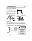
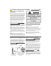
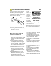
Tie a double overhand knot in one end of the Manual Release Rope and slip the other end through
the red Release Handle, the Release Instruction Card, and the hole at the end of the Release Lever on the Trolley.
Tie a second double overhand knot in the free end, adjusting the Rope so that the Red Handle is 6 FT above
the floor. If the Rope must be cut, flame seal the cut end with a match or lighter.
NOTE:
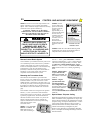
The MANUAL RELEASE MECHANISM is engaged by pulling the Release Handle down and
away from the door. This allows the Trolley Mechanism to separate, freeing the door from the Opener's
transport mechanism.
To re-engage, simply
move the MANUAL
RELEASE
MECHANISM Lever
forward and then
operate normally
using the Push
Button or Radio
Control. The two
parts of the Trolley
Mechanism will
automatically
reconnect.
DOUBLE
OVERHAND
KNOT
RELEASE
INSTRUCTION
CARD
DOUBLE
OVERHAND
KNOT
FLOOR
104378
WARNING
KEEP PEOPLE AND OBJECTS
OUT OF DOOR OPENING WHEN
USING MANUAL DISCONNECT.
AN OPEN OR PARTIALLY OPEN
DOOR MAY FALL
UNCONTROLLABLY IF
DISCONNECTED FROM
OPENER. CONTACT A
SERVICE PROFESSIONAL TO
CORRECT ANY DOOR
PROBLEMS.
DOOR
FULLY
OPEN
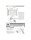
ALLOW 2” BETWEEN TOP
OF DOOR AND RAIL
104373
NOTE: The Model MVP-SQ is provided with vibration isolator
mounts. Position as shown above.
D
O
O
R
111205
MVP-SQ
104374
INSTALLING THE OPENER
7
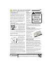
Secure Head Unit to
ceiling framing using angle
iron (not provided).


