


INSTALLATION OF 2 WIRE SAFE FINISH
PHOTOSYSTEM
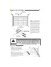
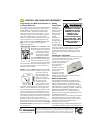
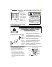
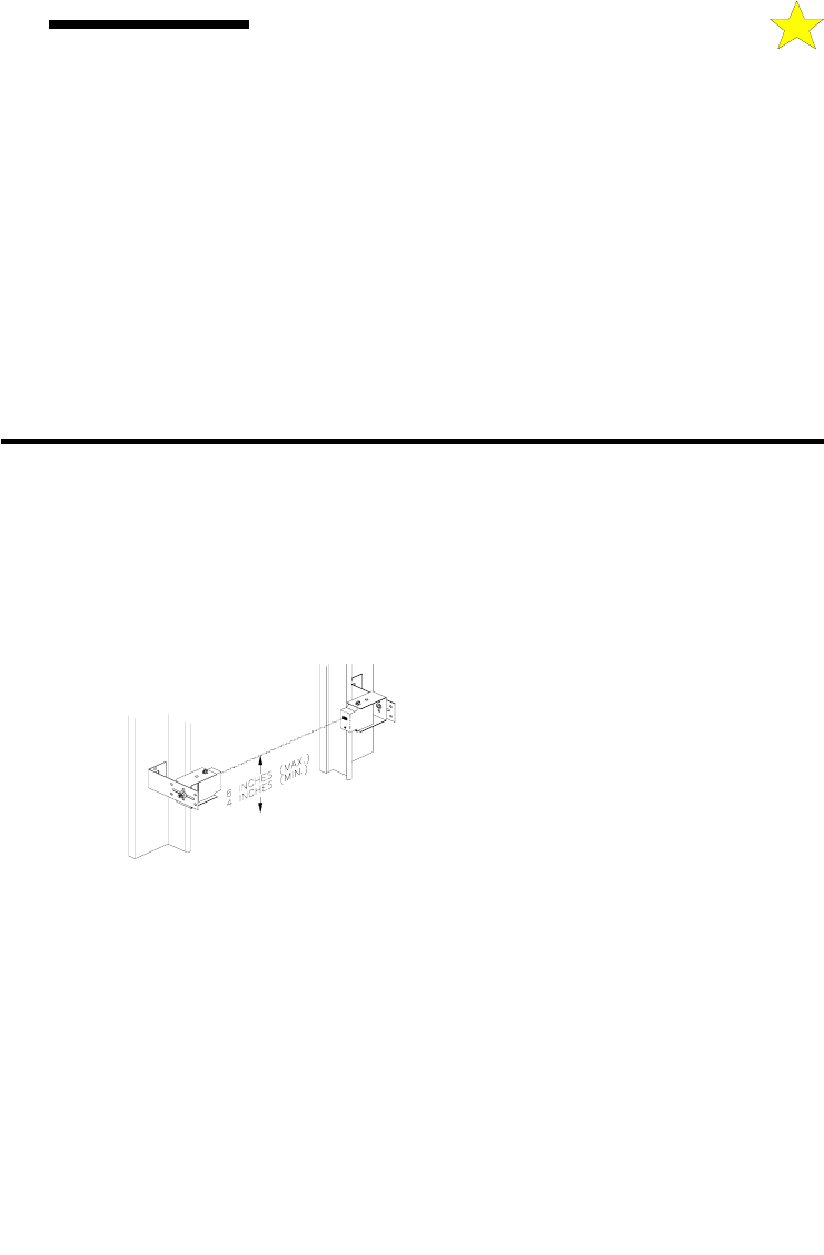
STEP 1: Mark the position of the SAFE
FINISH™ Photosystem as follows: Mark a line on
the left and right door jamb (close to the door track)
FOUR (4) inches AND SIX (6) inches above the
floor. The top mark is the maximum height and the
bottom line is the minimum height that the
photosystem
accessory can
be placed.
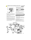
STEP 2:
Mount the
Photosystem
"L"
Brackets as
follows:
A. Remove
the four mounting brackets from the package.
Temporarily place the "U" shaped brackets, one
around the receiver (unit with window and red LED)
and one around the transmitter. NOTE: It is easier to
slip the photosystem units in from the side of the
bracket than forcing them in from the front of the
bracket.
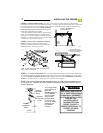
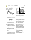
B.Your photosystem assembly is provided with a
universal bracket set. Using either the transmitter or
receiver (window up towards the ceiling), hold the "L"
bracket and the "U" bracket set together while moving
them in between the limit marks on the door jamb.
Continue to move the photosystem assembly within
the limit marks until it clears the door hardware. See
Illustration, left. Check to ensure the window on the
front of the photosystem unit is within the limit marks
on the door jamb.
C.Place a mark in the center of the lag screw elongated
mounting hole. Measure its position and place a
similar mark on the opposite door jamb. The brackets
may be temporarily mounted to the jamb with a 1" flat
head nail (provided) using the small hole above the
slot. Using two 5/16" X 1-1/2” lag screws (provided),
permanently mount the "L" bracket to both door
jambs.
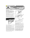
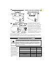
STEP 3: Connect the Photosystem as follows:
A.Remove the transmitter and receiver from their "U"
mounting brackets.
Refer to Page 22 for various wiring options for the
Safe Finish™ Photosystem. Steps B and C, below,
describe the wiring for Series Connection with
Receiver First, as illustrated on Page 19.
B.Run a wire pair (not supplied) around the garage
door jamb between the transmitter and receiver "L"
mounting brackets. NOTE: Leave about 12” of extra
wire at each end. Use a minimum 22 gauge solid
"trace" wire for interconnect.
C.Run a wire pair (20 or 22 gage solid wire) from the
receiver position (unit with "LED" light in the front,
may be either side of the door) back to the rear
bulkhead of the garage door opener. NOTE: Leave
about 12” of extra wire at the receiver end and about
24” of extra wire at the opener end.
D.Strip approximately 5/16” from each wire end at the
photosystem units and at the opener.
E.Using two (2) wire nuts (supplied), connect the wire
ends at the SAFE FINISH™ Photosystem transmitter
to the pigtail wire ends coming out of the transmitter
unit. Although not required, it is recommended to
connect the trace wire ends together and the unmarked
wire ends together.
104382
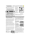
by moving approximately 45 feet back from the garage
door, then press the appropriate transmitter button that has
been programmed for that door. The red LED light will
illuminate on the front face of the transmitter. This is your
indication that a signal has been generated and sent out by
the transmitter (provided a valid programming sequence
has been done with the transmitter). Operation at this
distance should be reliable. However, environmental
conditions and the location of the transmitter and receiver
antenna will affect distance.
•
If the opener doesn’t activate check if the power head unit
has been programmed to accept the transmitter signal. The
red LED on the rear panel of the power head unit will blink
two times rapidly if it has accepted a valid transmitter
signal. If the LED light does not blink reprogram the MVP
power head unit to accept the transmitter signal by
following the previous instructions “Programming the
MVP Receiver Power Head Unit” making sure you
erase any previously learned signal (Step 1).
•
If the distance is inadequate check the battery and
replace if necessary.
•
If the distance is inadequate check the position of the
power head unit antenna (see above).
•
To maximize the operating distance move the
transmitter to different locations in the car until a
satisfactory distance is achieved. Vanity mirrors on
sun visors will affect performance.
If the HomeLink® transmitter does not activate the
operator or distance is inadequate, verify proper
operation using the transmitter packed with your
opener. Contact your HomeLink® system provider
for help with configuring the HomeLink® transmitter
and to resolve distance problems when using the
HomeLink® system.
CONTROL AND AUXILIARY EQUIPMENT
13