


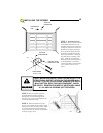
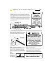
STEP 4: Run the wire from the Super Station to the
opener, supporting it at 18” intervals with suitable
staples. Leave a sufficient length to make the necessary
connections to the opener terminal strip.
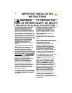
WARNING: SOME LOCAL BUILDING
CODES DO NOT ALLOW SURFACE WIRING.
BE SAFE AND CHECK WITH THE LOCAL
BUILDING INSPECTOR FIRST.
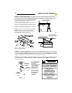
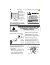
STEP 5: Ensure
power is OFF to the
opener or disconnect
the power from the
opener. Strip
approximately 4” of
jacket from the end of
the wire and 1/2”
insulation from each
wire. Connect to
terminals 0 and 1 as
shown in the
illustration above.
Support the wire near
the opener with wire
ties.
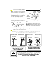
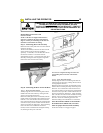
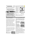
STEP 6: Install the Control Button Warning Label
supplied with your opener near the Super Station or
wall push button (see illustration at right).
!
Child can be pinned under automatic garage
door. Death or serious injury can result.
•
Never let child walk or run under moving door.
•
Never let child use door opener controls.
•
A
lways keep moving door in sight.
•
If person is pinned, push control button or use
emergency release.
•
Test door opener monthly:
Refer to
y
our owner’s manual
Place one-inch ob
j
ect
(
or 2x4 laid flat
)
on floor.
If door fails to reverse on contact, ad
j
ust o
p
ener.
If o
p
ener still fails to reverse door, re
p
air or re
p
lace o
p
ener.
WARNING
104350
CONTROL BUTTON
WARNING LABEL
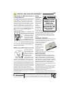
WARNING
IMPROPER DOOR OPERATION
COULD CAUSE INJURY OR DEATH.
WARNING LABEL MUST BE
MOUNTED ON WALL NEAR THE
PUSHBUTTON. ALL WARNINGS AND
INSTRUCTIONS ON THE LABEL
SHOULD BE STRICTLY ADHERED TO.
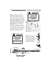
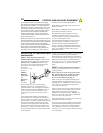
Remote Control Radio System
Your transmitter is pre-coded at the factory with one of
over 19,000 unique codes, and as such it is possible to
control a single opener or a group of openers at one
location or at multiple locations. Your transmitter may
be mounted on a visor using the metal visor clip
(included) or attached to a key-chain with the built-in
attachment. Your remote control radio system is
compatible with the HomeLink® systems.
Resetting the Transmitter Code
Each button of the transmitter is pre-coded at the
factory to one of over 19,000 unique codes. Follow the
instructions below to set your own code or to code
multiple buttons or transmitters to the same code. You
can record your code(s) on the back page of the manual.
If recoding is not desired, skip to “Programming the
Radio Receiver in the Power Head Unit” on the next
page.
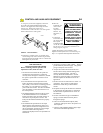
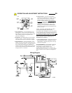
The transmitter codes are set using the three operation
buttons (+, O, and -) on the front of the transmitter.
There are three steps to set the code:
1- The transmitter
is placed in program mode;
2- the desired button is
selected; and
3- the code is entered. Any one of the
buttons or all three buttons may be coded by the
sequence outlined below. Also see Express Coding
under “Special Notes” at the
end of this section.
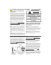
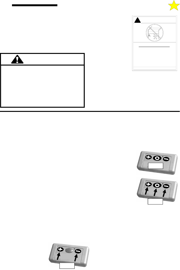
STEP 1: First, press and
hold the “+” button. The
RED LED will turn on.
Next, while continuing to
hole the “+” button, press and hold the “-” button.
Continue to hold both the “+” and “-” buttons until the
LED starts to blink (approximately 5 seconds). When
the LED starts to blink IMMEDIATELY release
both the “+” and “-” buttons. The LED will blink two
times and then remain on to confirm programming
mode.
STEP 2: While the LED is
on, press and release the
button you wish to code. The
LED will blink once and then
remain on.
STEP 3: Using the
operation buttons on the
front of the transmitter,
enter a 9-digit random code.
Every time a button is pressed
the LED will turn off and on.
After the 9-digit code is
entered, the LED will blink twice to confirm a valid code and
remain off.
Special Notes - Express Coding
Repeat the steps listed above as needed or desired for each
button. Each button can be programmed to a unique code,
however all three buttons may be programmed at one time
(Express Coding). To Express Code, select the “+” button
in Step 2, then end the code entry in Step 3 with the “+”
button (the first 8 entries can be any random code). The
code for each button may be changed at any time.
However, if the plus button is programmed as described
above, it will replace the existing code settings of the zero
and minus buttons.
Step 1
Step 2
Step 3
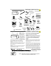
CONTROL AND AUXILIARY EQUIPMENT
11