


5
NOTE:
The Tee Rail/Chain Assembly is packaged separately from the Power Unit.
The Inner Trolley half, Front Idler Sprocket, Chain, Restraining Device and Limit Cams
are assembled on the Tee Rail at the factory. Follow the steps outlined below to
complete assembly prior to installation. Refer to the component identification
illustrations on the previous page.
STEP 1:
Protect the Power Unit cover from scratching during assembly by placing it on
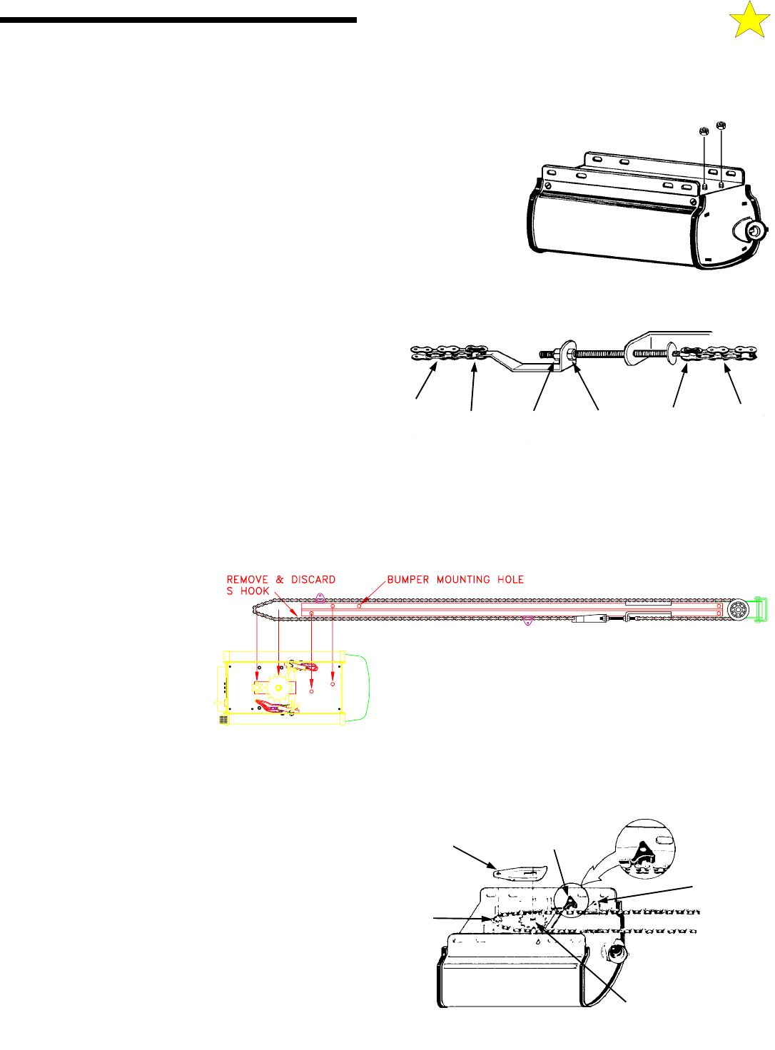
cardboard. Remove the two 5/16"-18 washered nuts and save them for later use.
STEP 2:
Position the Tee Rail/Chain Assembly box near the Power Unit. Open the box
and locate the Installation Hardware Packet.
STEP 3:
Locate the Outer Trolley half (packaged with the Power Unit) and slide it onto
the Tee Rail/Chain Assembly with the arrow on the Trolley pointing toward the Door
(Front Idler).
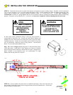
STEP 4:
Using a 1/2" wrench, loosen the outer nut on the Chain
Tension Bracket until it is at the end of the threaded rod. Remove
and discard the small "S" hook used to keep the chain tight
during shipping.
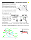
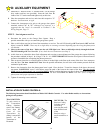
STEP 5:
Loop the chain around the Idler and Drive Sprocket on
top of the Power Unit and then position the Tee Rail on the studs.
Secure with the two nuts removed in Step 1.
Slightly tension the Chain by tightening the outer nut on the Chain
Tension Bracket. Remove and discard the tape at each end of the Tee Rail Assembly. After double-checking the Chain's alignment
with the Drive Sprocket and Front Idler Wheel, use the inner and outer adjusting nuts on the Chain Tension Bracket to adjust the chain
to the proper tension, making sure the chain does not twist. When correctly adjusted, the Chain should show no droop and be
approximately 1/2" above the base of the Tee Rail.
NOTE: If the chain is too loose or too tight, improper operation and/or excessive sprocket noise may result.
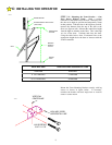
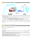
STEP 6:
Position the open and
close Limit Switch Actuators to
accept the Limit Cams on the chain,
as shown. Install the Chain Guard
by sliding the key-shaped hole onto
the groove on the Idler Sprocket
Shaft and fully seating the rear hole
over the Drive Sprocket Shaft. The
Limit Cams are installed at the
factory. Their settings should be
considered temporary and may be
changed as required during installation.
STEP 7:
Install the Rubber Bumper into its mounting hole on the Tee Rail (see illustration above for location). Secure the Bumper
to the bottom of the Tee Rail using one 5/16"-18 X 1" hex head bolt and one 5/16"-18 washered nut (supplied) Tighten the bolt a
MAXIMUM of 1.5 turns after the bolt and nut are snug.
STEP 8:
Recheck the nuts used to secure the Tee Rail to the
Power Unit, making sure they are tight. Recheck the Chain
tension, Chain twist, Chain Guard and the position of both the
Close Limit Switch and Open Limit Switch Actuators.
Assembly is now complete and you are ready to
begin installation of the opener.
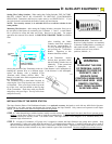
If Your Opener Is Supplied Fully Assembled, Please Disregard This Page.
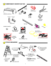
A:
ASSEMBLY INSTRUCTIONS
104363
CHAIN
MASTER
LINK
OUTER
NUT
INNER
NUT
MASTER
LINK
CHAIN
104364
104365
CHAIN
GUARD
CLOSE LIMIT
SWITCH
ACTUATOR
DOWN
LIMIT CAM
IDLER
SPROCKET
DRIVE
SPROCKET
104366