


12
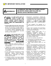
DISCONNECT POWER AT
FUSE BOX AND OPENER
BEFORE WIRING
PERMANENTLY TO
PREVENT
ELECTROCUTION.
WARNING
IMPROPER WIRING COULD
CAUSE ELECTROCUTION
OR DAMAGE TO
CIRCUITRY. FOLLOW
LOCAL BUILDING AND
WARNING
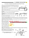
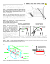
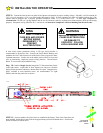
STEP 9:
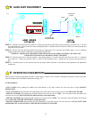
Consult the label on the rear panel of the Opener to determine its proper working voltage. Normally it will be marked for
115V, 60 cycle operation. (If it is an export model designed for 220V, 50 cycle operation, the label will clearly indicate this.) The
Opener must be plugged into a properly grounded receptacle within 3 FT of the Power Unit. A GFI Type receptacle is
recommended. Do not use 2-prong adapters and do not use extension cords for anything more than temporary hook-up and testing
purposes. Receptacle wiring should be No. 14 or heavier, and must be in compliance with local building and electrical codes.
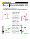
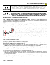
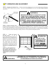
If local codes require permanent wiring, a GFI type circuit breaker is
recommended to protect the line. Remove the Strain Relief Bushing and
withdraw the Line Cord from the rear of the Power Unit to expose the three
insulated connectors. Cut the wire at the rubber jacket of the Line Cord and
wire in permanently, employing proper wiring practices. Discard Strain
Relief. It is not used with permanent wiring.
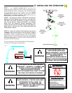
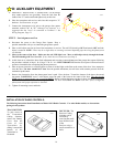
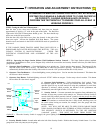
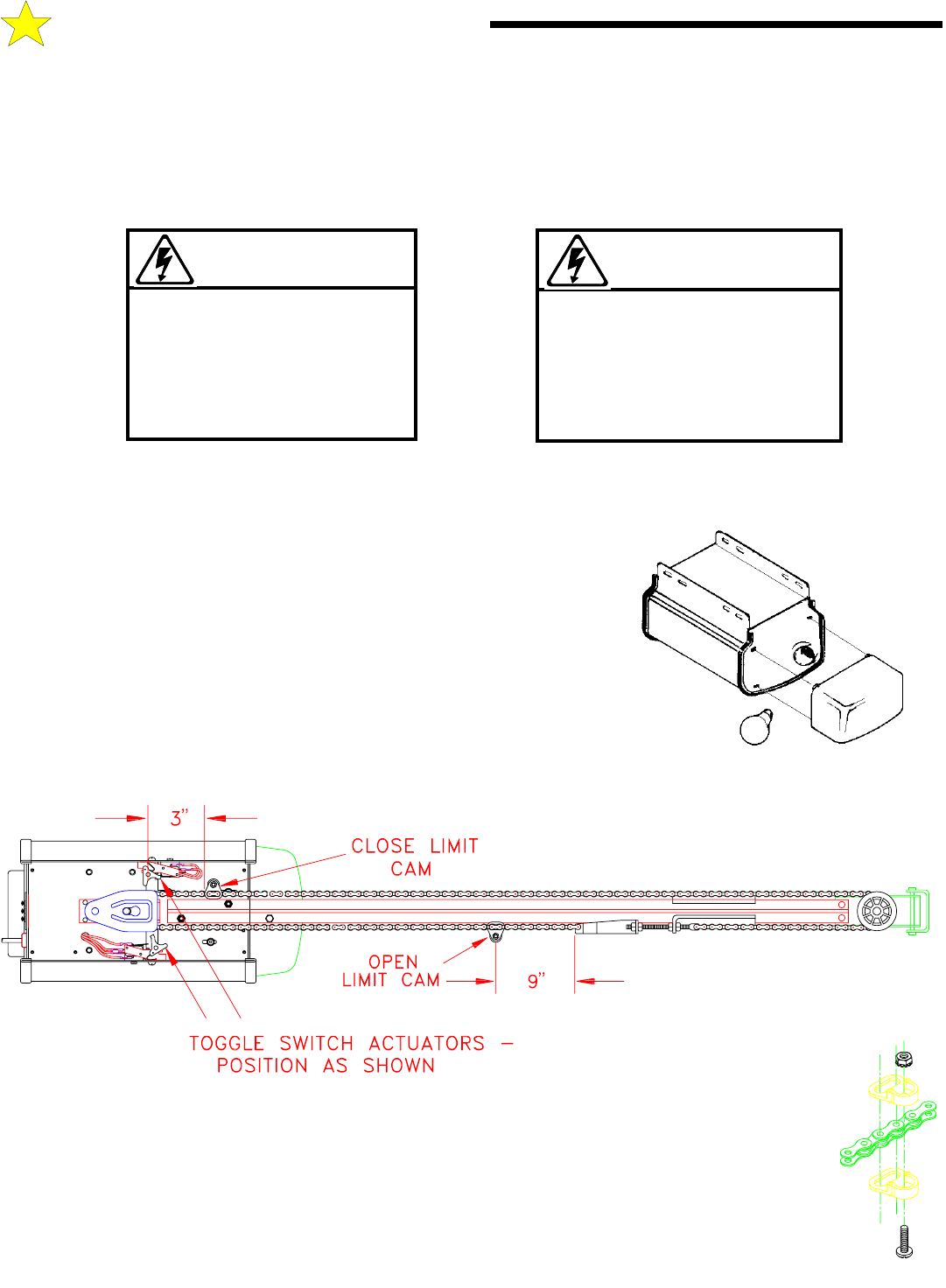
Step 10:
Install a Rough Service lamp bulb (75 Watt maximum) firmly
in the light socket. Light bulbs in Door Openers are subject to vibration
during normal operation which may shorten their life spans. Rough Service
bulbs, available at most hardware stores, are recommended. Fit Light
Diffuser tabs into the panel slots as shown.
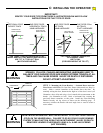
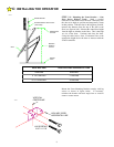
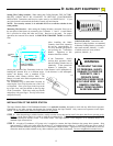
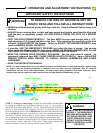
STEP 11:
On most models, the Limit Cams are installed at the factory. If the Limit Cams have not
been installed, fasten them to the Chain in the approximate positions illustrated above. Position the
Switch Actuators as shown above.
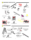
104380
104381
106428
C:
INSTALLING THE OPERATOR
FASTENING
LIMIT CAM TO
CHAIN