


16
D:
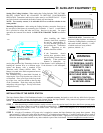
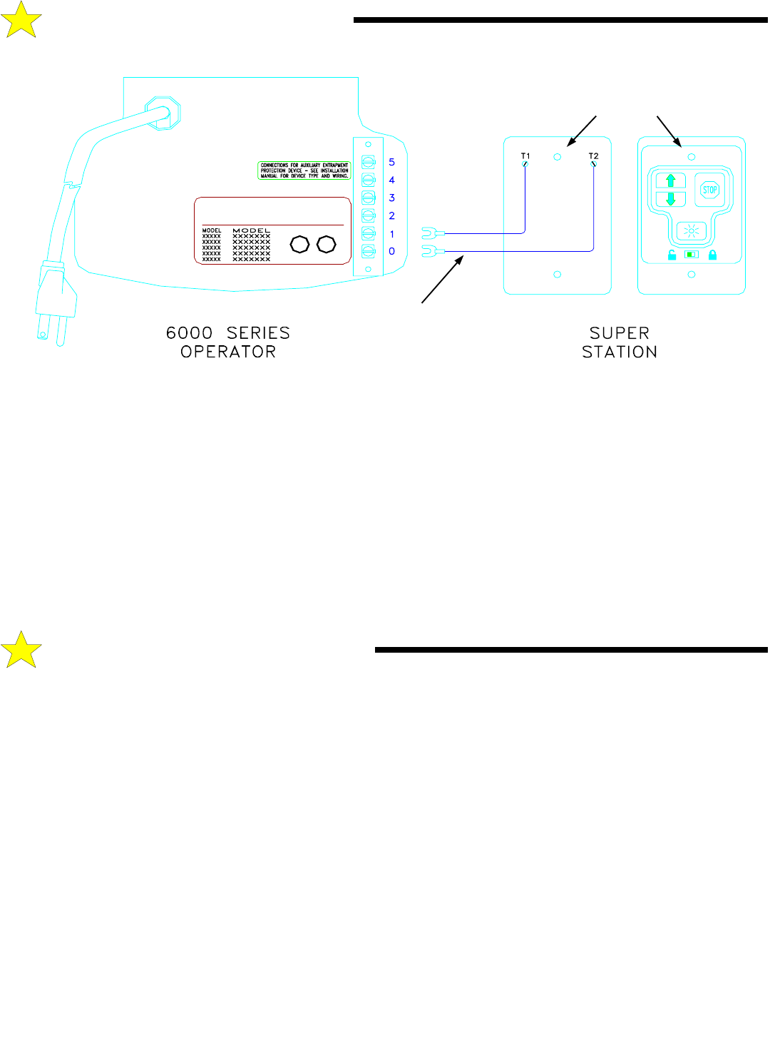
AUXILIARY EQUIPMENT
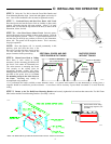
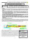
STEP 3:
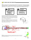
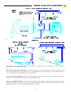
Push the wire jacket into one of the two notches provided at the ends of the housing, allowing a maximum of 1/8” inch of
the jacket inside the case (too much will make mounting difficult). Carefully tuck the loose wires into the case and mount the unit
using the screws provided.
STEP 4:
Run the wire from the Super Station to the operator, supporting it at 18” intervals with suitable staples. Leave a sufficient
length to make the necessary connections to the operator terminal strip.
WARNING: SOME LOCAL BUILDING CODES DO NOT ALLOW SURFACE WIRING. BE SAFE AND
CHECK WITH YOUR LOCAL BUILDING INSPECTOR FIRST.
STEP 5:
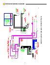
Disconnect the power from the operator. Strip approximately 4” of jacket from the end of the wire and 1/2” insulation
from each wire. Connect to terminals 0 and 1 as shown in the illustration above. Support the wire near the operator with wire
ties.
STEP 6:
Reconnect power to the operator and test the Super Station functions as described in the Operation and Adjustment
Instructions.
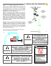
Please note the following Operating Parameters which apply to Openers with Auxiliary Entrapment Protection System connected.
(All-Clear Photosystem, Installation Instructions on Page 13.)
IF THE DOOR IS...
...FULLY OPEN, then pushing the standard wall Push Button or the radio control will cause the door to begin MOVING
DOWNWARD.
...FULLY CLOSED, then pushing the wall Push Button or the radio control will cause the door to begin MOVING UPWARD.
...MOVING UPWARD, then pushing the wall Push Button will cause the door to STOP. The next push of the wall button will
cause the door to begin MOVING DOWNWARD (Alternate Action Operation).
...MOVING UPWARD, then pushing the radio control will cause the door to STOP. The next push of the wall button will cause the
door to RESUME UPWARD MOVEMENT (Radio Operation).
...MOVING DOWNWARD, then pushing the wall Push Button or the radio control will cause the door to STOP, PAUSE FOR
APPROXIMATELY ONE SECOND, AND THEN BEGIN MOVING UPWARD.
E:
OPERATING PARAMETERS
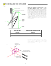
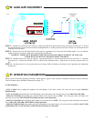
2-CONDUCTOR
22 GAUGE WIRE
MOUNTING
HOLES
BACK
FRONT
108387