


506725-01 Page 43 of 48
Issue 1109
19. Reinstall heat exchanger into cabinet making sure that
the clamshells of the heat exchanger assembly are
resting on the support located at the rear of the cabinet.
Remove the indoor blower to view this area through the
blower opening.
20. Resecure the supporting screws along the vestibule
sides and bottom to the cabinet. Reinstall blower and
mounting screws.
21. Reinstall cabinet screws on front flange at blower deck.
22. Reinstall the primary limit on the vestibule panel.
23. Route heating component wiring through hole in blower
deck and reinsert strain relief bushing.
24. Reinstall electrical junction box.
25. Reinstall the combustion air inducer. Reconnect the
combustion air inducer to the wire harness.
26. Reinstall pressure switches and reconnect pressure
switch wiring.
27. Carefully connect combustion air pressure switch hosing
from pressure switches to proper stubs on cold end
header collector box.
28. Reinstall condensate trap.
29. Reconnect exhaust piping and exhaust drain tubing.
30. Reinstall burner box assembly in vestibule area.
31. Reconnect flame rollout switch wires.
32. Reconnect sensor wire and reconnect 2 pin plug from
ignitor.
33. Secure burner box assembly to vestibule panel using
four existing screws. Make sure burners line up in
center of burner ports.
34. Reinstall gas valve manifold assembly. Reconnect gas
supply line to gas valve.
35. Reconnect 2 wires to gas valve.
36. Replace the blower compartment access panel.
37. Refer to instruction on verifying gas and electrical
connections when re-establishing supplies.
38. Follow lighting instructions to light and operate furnace
for 5 minutes to ensure that heat exchanger is clean
and dry and that furnace is operating properly.
39. Replace heating compartment access panel.
Cleaning the Burner Assembly
1. Turn off electrical and gas power supplies to furnace.
Remove upper and lower furnace access panels.
2. Disconnect the 2 pin plug from the gas valve.
3. Remove the burner box cover.
4. Disconnect the gas supply line from the gas valve.
Remove gas valve/manifold assembly.
5. Mark and disconnect sensor wire from the sensor.
Disconnect 2 pin plug from the ignitor at the burner box.
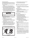
6. Remove four screws which secure burner box assembly
to vest panel. Remove burner box from the unit.
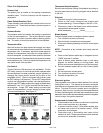
7. Use the soft brush attachment on a vacuum cleaner to
gently clean the face of the burners. Visually inspect
the inside of the burners and crossovers for any blockage
caused by foreign matter. Remove any blockage.
8. Reconnect the sensor wire and reconnect the 2 pin plug
to the ignitor wiring harness.
9. Reinstall the burner box assembly using the existing four
screws. Make sure that the burners line up in the
center of the burner ports.
10. Reinstall the gas valve manifold assembly. Reconnect
the gas supply line to the gas valve. Reinstall the burner
box cover.
11. Reconnect 2 pin plug to gas valve.
12. Replace the blower compartment access panel.
13. Refer to instruction on verifying gas and electrical
connections when re-establishing supplies.
14. Follow lighting instructions to light and operate furnace
for 5 minutes to ensure that heat exchanger is clean
and dry and that furnace is operating properly.
15. Replace heating compartment access panel.