


506725-01Page 14 of 48 Issue 1109
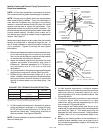
Joint Cementing Procedure
All cementing of joints should be done according to the
specifications outlined in ASTM D 2855.
1. Measure and cut vent pipe to desired length.
2. Debur and chamfer end of pipe, removing any ridges or
rough edges. If end is not chamfered, edge of pipe
may remove cement from fitting socket and result in a
leaking joint.
3. Clean and dry surfaces to be joined.
4. Test fit joint and mark depth of fitting on outside of pipe.
5. Uniformly apply a liberal coat of PVC primer for PVC or
use a clean dry cloth for ABS to clean inside socket
surface of fitting and male end of pipe to depth of fitting
socket.
6. Promptly apply solvent cement to end of pipe and inside
socket surface of fitting. Cement should be applied
lightly but uniformly to inside of socket. Take care to
keep excess cement out of socket. Apply second coat
to end of pipe.
NOTE: Time is critical at this stage. Do Not allow Primer to
dry before applying cement.
7. Immediately after applying last coat of cement to pipe,
and while both inside socket surface and end of pipe
are wet with cement, forcefully insert end of pipe into
socket until it bottoms out. Turn PVC pipe 1/4 turn during
assembly (but not after pipe is fully inserted) to distribute
cement evenly. Do not turn ABS or cellular core pipe.
NOTE: Assembly should be completed within 20 seconds
after last application of cement. Hammer blows should not
be used when inserting pipe.
8. After assembly, wipe excess cement from pipe at end
of fitting socket. A properly made join will show a bead
around its entire perimeter. Any gaps may indicate an
improper defective assembly due to insufficient solvent.
9. Handle joints carefully until completely set.
DANGER OF EXPLOSION!
Fumes from PVC glue may ignite during system check.
Allow fumes to dissipate for at least 5 minutes before
placing unit into operation.
DANGER
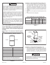
FIGURE 17
* See Table 4 for allowable pipe.
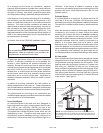
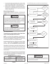
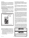
Piping Suspension Guidelines
NOTE: Isolate piping at the point where it exits the outside wall or
roof in order to prevent transmission of vibration to the structure.
SCHEDULE 40
PVC − 5’
all other pipe* − 3’
Wall
edistuoedisni
24" maximum
3/4" minimum
Wall Thickness Guidelines
insulation
(if required)
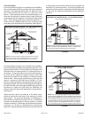
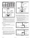
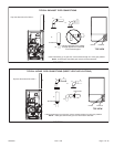
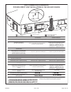
CHIMNEY
OR GAS
VENT
(Check sizing
for remaining
appliance)
FURNACE
(Removed from
from common
vent system)
WATER
HEATER
OPENINGS
(To Adjacent
Room)
If this gas furnace replaces a furnace which was
commonly vented with another gas appliance,
the size of the existing vent pipe for that gas ap-
pliance must be checked. Without the heat of the
original fur
nace ue products, the existing vent pipe
is probably oversized for the single water heater or
other appliance. The vent should be checked for
proper draw with the remaining appliance.
FIGURE 18
REPLACING FURNACE THAT
WAS PART OF A COMMON
VENT SYSTEM
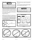
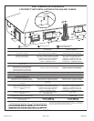
NOTE: A sheet metal screw may be used to secure the
intake pipe to the connector, if desired. Use a drill or self
tapping screw to make a pilot hole.
Venting Practices