


506725-01Page 10 of 48 Issue 1109
WARNING
Improper installation of the furnace can result in personal
injury or death. Combustion and flue products must
never be allowed to enter the return air system or air in
the living space. Use sheet metal screws and joint tape
to seal return air system to furnace.
In platform installations with furnace return, the furnace
should be sealed airtight to the return air plenum. A
door must never be used as a portion of the return air
duct system. The base must provide a stable support
and an airtight seal to the furnace. Allow absolutely no
sagging, cracks, gaps, etc.
For no reason should return and supply air duct systems
ever be connected to or from other heating devices such
as a fireplace or stove, etc. Fire, explosion, carbon
monoxide poisoning, personal injury and/or property
damage could result.
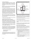
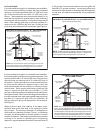
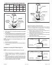
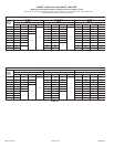
Installation on Non-Combustible Flooring (Figure 12)
1. Cut floor opening keeping in mind clearances listed on
unit rating plate. Also keep in mind gas supply
connections, electrical supply, flue and air intake
connections and sufficient installation and servicing
clearances. See Table 1 for correct floor opening size.
2. Flange warm air plenum and lower the plenum into the
opening.
3. Set the unit over the plenum and seal the plenum to the
unit.
4. Ensure that the seal is adequate.
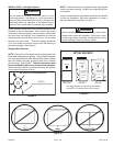
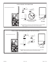
Installation on Combustible Flooring (Figure 13)
1. When unit is installed on a combustible floor, a downflow
combustible flooring base must be installed between the
furnace and the floor. The base must be ordered
separately. See Table 2 for opening size to cut in floor.
CAUTION
The furnace and combustible flooring base shall not be
installed directly on carpeting, tile, or other combustible
material other than wood flooring.
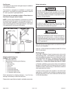
The unit may be installed three ways in downflow applica-
tions: on non-combustible flooring, on combustible flooring
using an additive base, or on a reverse-flow cooling coil
cabinet. Do not drag the unit across the floor in the
downflow position. Floor and furnace flange damage
will result.
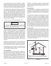
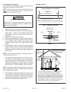
Refer to Figure 11 for clearances in downflow applica-
tions.
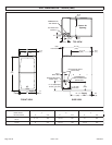
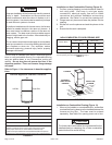
Downflow Application Installation Clearances
Top
Bottom
Left Side Right Side
Top 0
*Front 0
Back 0
Sides 0†
Vent 0
Floor NC ‡
*Front clearance in alcove installation must be 24 in. (610 mm).
Maintain a minimum of 24 in. (610 mm) for front service access.
†Allow proper clearances to accommodate condensate trap.
‡The furnace may be installed on a combustible wood oor if an optional
additive base is installed between the furnace and the combustible oor.
FIGURE 11
FIGURE 12
SUPPLY AIR
PLENUM
PROPERLY
SIZED FLOOR
OPENING
FURNACE
TABLE 1
NON−COMBUSTIBLE FLOOR OPENING SIZE
Cabinet Width
Front to Rear Side to Side
in. mm in. mm
B Cabinet (17.5") 19 − 3/4 502 16 − 5/8 422
C Cabinet (21") 19 − 3/4 502 20−1/8 511
NOTE: Floor opening dimensions listed are 1/4 inch (6 mm) larger than
the unit opening. See dimension drawing on page 2.