


506725-01Page 32 of 48 Issue 1109
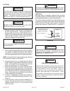
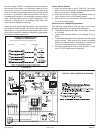
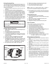
One line voltage “HUM” 1/4” spade terminal is provided on
the furnace control board. Any humidifier rated up to one
amp can be connected to this terminal with the neutral leg
of the circuit being connected to one of the provided neutral
terminals. If a humidifier rated at greater than one amp is
connected to this terminal, it is necessary to use an external
relay. See Figure 49 for control board configuration. This
terminal is energized in the heating mode when the
combustion air inducer is operating.
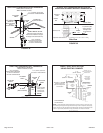
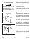
Install the room thermostat according to the instructions
provided with the thermostat. See Figure 46 for thermostat
designations. If the furnace is being matched with a heat
pump, refer to the FM21 installation instruction or appropriate
dual fuel thermostat instructions.
Generator Use - Voltage Requirements
The following requirements must be kept in mind when
specifying a generator for use with this equipment:
• The furnace requires 120 volts ± 10% (Range: 108 volts
to 132 volts).
• The furnace operates at 60 Hz ± 5% (Range: 57 Hz to
63 Hz).
• The furnace integrated control requires both polarity and
proper ground. Both polarity and proper grounding
should be checked before attempting to operate the
furnace on either permanent or temporary power.
• Generator should have a wave form distortion of less
than 5% THD (total harmonic distortion).
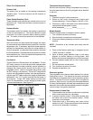
Indoor Blower Speeds
1. When the thermostat is set to “FAN ON”, the indoor
blower will run continuously on the heating speed when
there is no cooling or heating demand.
2. When the furnace is running in the heating mode, the
indoor blower will run on the heating speed.
3. When there is a cooling demand, the indoor blower will
run on the cooling speed.
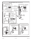
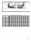
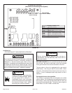
Thermostat Furnace Condensing
Unit
FURNACE and CONDENSING UNIT
THERMOSTAT DESIGNATIONS
(Refer to specic thermostat and outdoor unit.)
COMMON
POWER
HEAT
INDOOR BLOWER
Y
C
R
G
W1
Y
C
R
G
W
COOLING
FIGURE 46
CONDENSING
CONDENSING
*CONDENSING
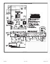
TYPICAL FIELD WIRING DIAGRAM
FIGURE 47
IGNITOR
*R