


506471-01Page 36 of 41 Issue 1034
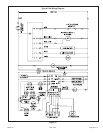
CONTROL DIAGNOSTICS
Troubleshooting
Make the following visual checks before troubleshooting:
1. Check to see that the power to the furnace and the
integrated ignition/blower control board is ON.
2. The manual shutoff valves in the gas line to the furnace
must be open.
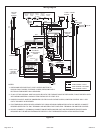
3. Make sure all wiring connections are secure.
4. Review the Sequence of Operation (see page 31).
Start the system by setting thermostat above room
temperature. Observe system response. Then use the
information provided in this section to check the system
operation.
The furnace has a built-in, self-diagnostic capability. If a
system problem occurs, a fault code is shown by a red LED
on the control board. The control continuously monitors its
own operation and the operation of the system. If a failure
occurs, the LED will indicate the failure code. The flash
codes are presented in Table 13
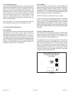
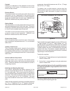
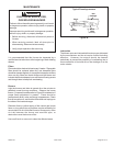
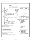
Fault Code History Button
The control stores the last five fault codes in memory. A
pushbutton switch is located on the control (see Figure 40
on page 38). When the pushbutton switch is pressed and
released, the control flashes the stored fault codes. The
most recent fault code is flashed first; the oldest fault code
is flashed last. To clear the fault code history, press and
hold the pushbutton switch in for more than 5 seconds before
releasing.
High Heat State LED
On A80UH2V and 80G1UH2V models, a green LED is
provided on the control board to indicate high heat state
(see Table 14).
CFM LED
On A80UH2V and 80G1UH2V models equipped with a
variable speed motor, an amber LED is provided on the
control board to display CFM. To determine what CFM the
motor is delivering at any time, count the number of times
the amber LED flashes. Each flash signifies 100 CFM; count
the flashes and multiply by 100 to determine the actual CFM
delivered (for example: 10 flashes x 100 = 1000 CFM).
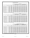
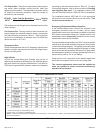
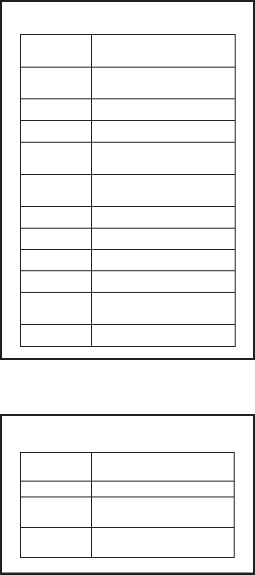
Failure Codes - Red LED
Table 13
LED Status Fault Description
LED Off
LED On
1 Flash Flame Present with gas valve off
2 Flashes
Pressure switch closed with
inducer off
Normal operation
No power to control or control
hardware fault detected
3 Flashes
Low-fire pressure, rollout, or aux
limit switch open
4 Flashes
High limit switch open
5 Flashes Not used
6 Flashes Pressure switch cycle lockout
7 Flashes Lockout due to no ignition
8 Flashes
Lockout due to too many flame
dropouts
9 Flashes Incorrect polarity and phasing
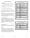
High Heat State - Green LED
Table 14
LED
Status
Description
LED Off
LED On
LED Flashing
No demand for high heat
High heat demand, operating
normally
High heat demand, high pressure
switch not closed