


506471-01 Page 13 of 41Issue 1034
Venting
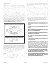
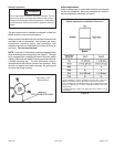
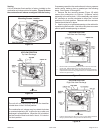
A 4 inch diameter flue transition is factory installed on the
combustion air inducer outlet of all models. Figure 16 shows
the combustion air inducer as shipped from the factory.
The unit will not vent properly with the flue transition
pointed down in the 6 o’clock position.
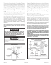
The combustion air inducer may be rotated clockwise
or counterclockwise by 90° to allow for top or side vent
discharge in all applications. When the unit is installed,
the flue transition must be in the 9 o’clock, 12 o’clock or
3 o’clock position.
IMPORTANT
If necessary reposition the combustion air inducer, pressure
switch and/or make-up box as needed per the following
steps. See Figures 16 through 22.
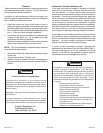
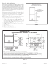
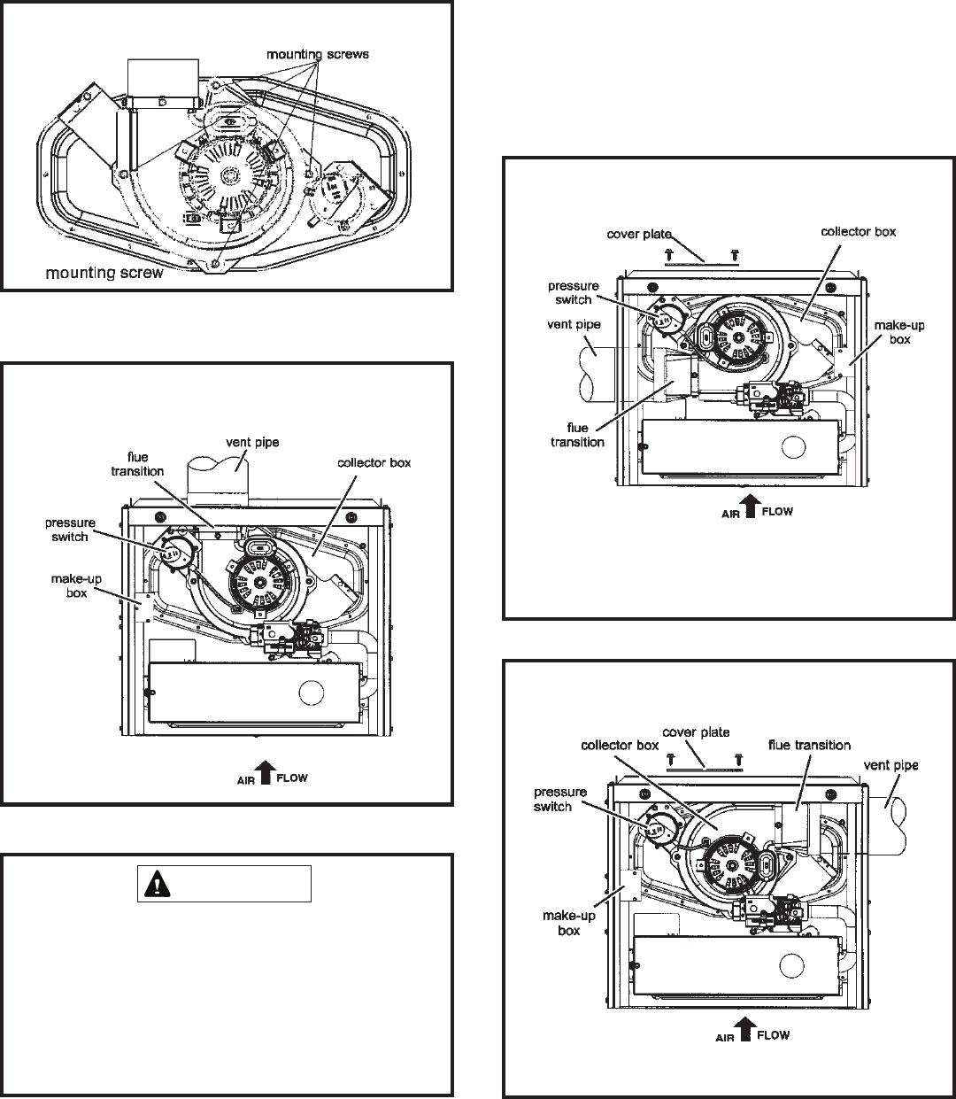
1. Remove the four mounting screws (Figure 15) which
secure the combustion air inducer / pressure switch
assembly to the orifice plate. Lift the assembly and rotate it
90° clockwise or counter clockwise to either the 3 o’clock
position or 9 o’clock position. Resecure with four secrews.
Gasket should be left in place.
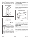
2. Use tin snips to cut preferred opening on the cabinet for
repositioning the flue outlet. Use the cut-out piece as a cover
plate to patch unused opening on cabinet.
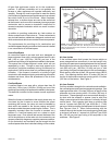
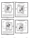
Figure 17
• Remove make-up box assembly (2 screws) and cut wire tie to free make-
up box wires. Reinstall make-up box on other side of cabinet.
• Resecure make-up box wires: Either pull excess wires through the blower
companrtment and secure using supplied wire tie, or coil excess wire and
secure to the gas manifold.
UPFLOW POSITION
Left Side Vent Discharge
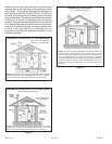
Figure 18
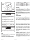
UPFLOW POSITION
Right Side Vent Discharge
• Pressure switch tubing may be too long. Cut to fit, then reattach to barbed
fitting on pressure switch. Tubing must not be allowed to sag.
UPFLOW POSITION
Top Vent Discharge
Figure 16
Mounting Screws Location
Figure 15