


506471-01Page 14 of 41 Issue 1034
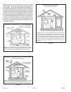
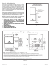
Horizontal Position
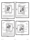
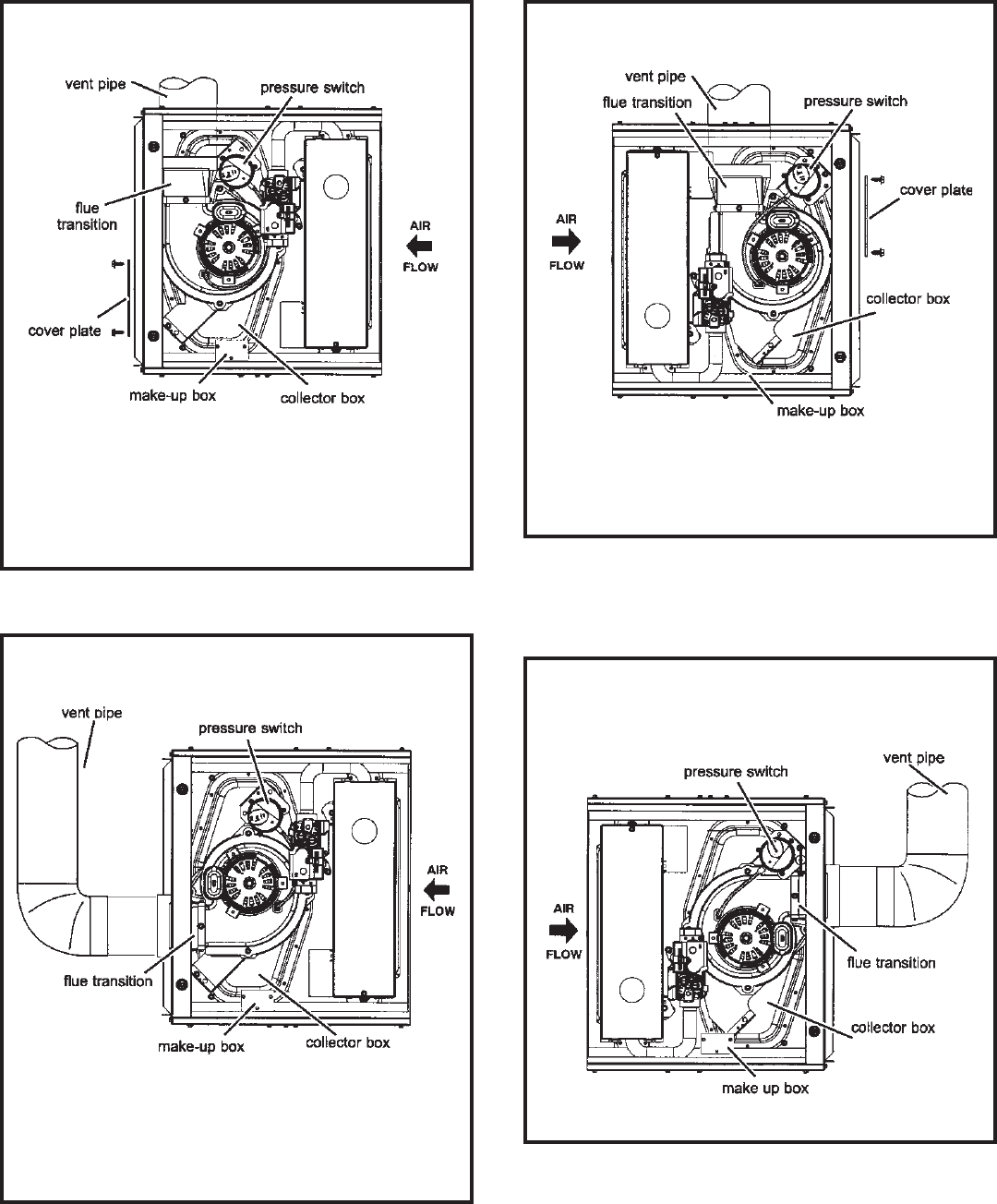
HORIZONTAL LEFT POSITION
Top Vent discharge
Figure 19
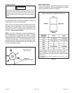
• Disconnect pressure switch hose from barbed fitting on the pressure
switch assembly. Remove pressure switch assembly (1 screw) and cut
wire tie to free pressure switch wires. Reinstall pressure switch on the
other side of orifice plate and reconnect pressure switch hose.
• Resecure pressure seitch wires: Either pull excess wires through the
blower compartment and secure using supplied wire tie, or coil excess
wire and secure to the gas manifold.
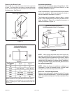
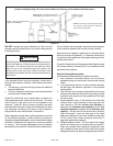
HORIZONTAL RIGHT POSITION
Top Vent Discharge
Figure 21
• Remove make-up box assembly (2 screws) and cut wire tie to free make-
up box wires. Reinstall make-up box on other side of cabinet.
• Resecure make-up box wires: Either pull excess wires through the blower
compartment and secure using supplied wire tie, or coil excess wire and
secure to the gas manifold.
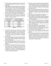
HORIZONTAL RIGHT POSITION
Side Vent Discharge
Figure 22
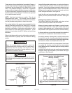
HORIZONTAL LEFT POSITION
Side Vent Discharge
Figure 20
• Disconnect pressure switch hose from barbed fitting on the pressure
switch assembly. Remove pressure switch assembly (1 screw) and cut
wire tie to free pressure switch wires. Reinstall pressure switch on the
other side of orifice plate and reconnect pressure switch hose.
• Resecure pressure seitch wires: Either pull excess wires through the
blower compartment and secure using supplied wire tie, or coil excess
wire and secure to the gas manifold.